Today I have rebuilt my preamplifier ( 80db ) With the LT1128 opamp in the first stage with suitably small resistors. Stage 2 with, what appears to be the one genuine NE5534, an old one made by Philips, the others were supposed to be TI, but they are much noisier than the Philips one, so I am guessing they were fakes, Blasted EBay!!!
Anyway broadband noise is pretty good but I'm still getting 50 & 100 Hz breakthrough despite star grounding. I am hoping that the synchronous detector and low pass filter can iron out this problem.
Anyway broadband noise is pretty good but I'm still getting 50 & 100 Hz breakthrough despite star grounding. I am hoping that the synchronous detector and low pass filter can iron out this problem.
Today has been a busy day. I have gotten the synchronous detector to work, but a new problem has arisen, in the form of bleed through of the reference signal into the amplifier chain. I am going to try switching to a differential input, to see if that helps.The other issue is correction for phase shift between the signal and the reference, this is probably going to be a nuisance when taking CCS measurements at several test frequencies, as the phase shift will also need to be adjusted in each case.
Below 1Khz the phase shift is small and doesn't impact significantly on the measured results.
Below 1Khz the phase shift is small and doesn't impact significantly on the measured results.
use the quietest opamp as the first stage of your multi-stage +80dB LNA.
Make sure the LV coming from the rectifier feeds one end of the PSU and that the PSU outputs at the other end.
Use twisted pairs for all inter module connections.
Consider adding some RC to a basic rC PSU and maybe an (L+r)C as well or instead.
eg
rC(L+r)CRC for three sets of cascaded filters.
All the wiring from the transformer secondaries, rectifier, rC, (L+r)C and RC must all have minimised loop areas. Twist every wire pair, even if only 30mm long.
Your measurements should allow you to see each wiring improvement. Individually all may be quite small, but the aggregate could be significant.
Last edited:
use the quietest opamp as the first stage of your multi-stage +80dB LNA.
This, I have done already, LT1128 in the first stage, I think that is about the quietest opamp for low source impedances, The current sense resistor is now 100 ohms. The signal to noise ratio is still better than with the 1K resistor, due to resistor noise and current noise ( 10 times higher with a 1k source than a 100 R source.
Make sure the LV coming from the rectifier feeds one end of the PSU and that the PSU outputs at the other end.
Can you clarify this a bit more for me, what do you mean by LV?
Consider adding some RC to a basic rC PSU and maybe an (L+r)C as well or instead.
eg
rC(L+r)CRC for three sets of cascaded filters.
I Tried one LC stage, but it wasn't enough, I will try what you suggested.
Use twisted pairs for all inter module connections.
All the wiring from the transformer secondaries, rectifier, rC, (L+r)C and RC must all have minimised loop areas.
Twist every wire pair, even if only 30mm long.
Sounds like a good plan will try this. My current layout is a mess, but I wasn't sure of the best practical steps to correct it.
Your measurements should allow you to see each wiring improvement. Individually all may be quite small, but the aggregate could be significant.
Thank you for all your advice, will probably have to wait until tomorrow to try out these ideas.
in at one end and out at the other end
Most PSU show the C and RC as a string of components across the page.
If your transformer and rectifier are at one side then the input to the PSU is at the same side. ALL the transformer secondaries connect to the PSU at the same side as the transformer.
The output is at the other side. The output wires (all of them) must come from the end remote from the transformer.
Many SCH show GND symbols and give no guidance on where to place these.
I am telling you where to place them.
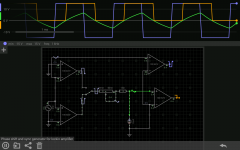
I have come up with something to allow for phase correction of the reference signal. The circuit as shown allows for around +/- 90° at 1 KHz, for other frequencies different capacitors will need to be switched into place.
The waveforms in the simulation, are:
Blue: The uncorrected reference signal ( shown only for comparison. )
Green: The capacitor charging / discharging waveform
Orange: The corrected reference signal
The switch selects leading or lagging phase. As shown the reference lags behind the input.
The waveforms in the simulation, are:
Blue: The uncorrected reference signal ( shown only for comparison. )
Green: The capacitor charging / discharging waveform
Orange: The corrected reference signal
The switch selects leading or lagging phase. As shown the reference lags behind the input.
Attachments
Last edited:
Having failed to eliminate breakthrough of the synchronization signal into the low noise amplifier, I have decided to assemble it ( the amplifier ) in a separate metal box ( I have one ) and have it powered by batteries, which brings me to the subject of this post. The charging of NiMH batteries. I have perused several practical approaches to doing so. I came across the following specification for the ultimate NiMH battery charger:
The Ultimate Charger:
1. Soft start. If the temperature is above 40 degrees C or below zero degrees C start with a C/10 charge. If the discharged battery voltage is less than 1.0 Volts/cell start with a C/10 charge. If the discharged battery voltage is above 1.29 V/cell start with a C/10 charge.
2. Option: if the discharged battery voltage is above 1.0 Volts/cell, discharge the battery to 1.0 V/cell then proceed to rapid charge.
3. Rapid charge at 1 C until the temperature reaches 45 degrees C, or the dT/dt indicates full charge.
4. After terminating the fast charge, slow charge at C/10 for 4 hours to ensure a full charge.
5. If the voltage climbs to 1.78 V/cell without otherwise terminating, terminate.
6. If the time on fast charge exceeds 1.5 hours without otherwise terminating, terminate the fast charge.
7. If the battery never reaches a condition where the fast charge starts time out the slow charge after 15 hours.
8. Fuel gauge, communication to the device being powered, LED indicators all possible.
This is the actual spec of a commercial microprocessor controlled unit, however I thought it would be a challenge to build a charger to this spec using old school technology, no microcontrollers, etc, just 4000B logic and opamps and discrete parts.
In comparison Lead/Acid is easy.
I would agree and was surprised at how reasonably priced a suitable battery would be.
I found this: Yuasa yucel 12v 1.2Ah Battery
I was doing some noise calculations and it would seem that a 10k current sense resistor and a tl072, would yield a better signal to noise ratio than a 100 ohm sense resistor and an LT1128. I was surprised and will carry out further investigations.
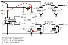
I have attached a possible battery power supply using an ICL7660S with LC filtering. Output ripple was just under 1mV RMS at a frequency of approximately 17Khz.
I have attached a possible battery power supply using an ICL7660S with LC filtering. Output ripple was just under 1mV RMS at a frequency of approximately 17Khz.
Attachments
You could consider adding low-valued resistors between the ICL7660's supply pins and the board level supply networks, as shown in red below. These resistors smear out the very fast, very steep current pulses that the chargepump IC's switches (and switch drivers) squirt onto the supplies. The less noise you put on the supplies, the less to worry about.
I'd recommend choosing a resistance that puts about (10% of supply) across each resistor, as measured peak-to-baseline on a fast oscilloscope. Since Ry is grounded, that's the easy one to measure; install several different Ry values until you find the one where V(Ry)_peak = 0.90 volts. Then set Rx=Ry, done.
If the chargepump is driving the V- supply pins of a couple LT1128 opamps, I'm guessing that Rx and Ry might be in the vicinity of 0.4 to 2.0 ohms but that's just a guess.
Attachments
You could consider adding low-valued resistors between the ICL7660's supply pins and the board level supply networks, as shown in red below. These resistors smear out the very fast, very steep current pulses that the chargepump IC's switches (and switch drivers) squirt onto the supplies. The less noise you put on the supplies, the less to worry about.
I'd recommend choosing a resistance that puts about (10% of supply) across each resistor, as measured peak-to-baseline on a fast oscilloscope. Since Ry is grounded, that's the easy one to measure; install several different Ry values until you find the one where V(Ry)_peak = 0.90 volts. Then set Rx=Ry, done.
Thanks Mark, I will keep this in mind when using the icl7660 in future. As regards my amplififier, I found a little Recom dc-dc module I bought from someone on eBay a few years ago, I wasn't sure if it actually worked as I'd never actually tested it. It turns out that it works and quite well. 9-36 vdc in +/-15 V out. It is very quiet too. With my CLC filter no ripple is visible on my scope.
I am quite scunnered with the CCS project for now. So have been experimenting with rechargeable batteries. The local pound shop has cheap NiMH batteries. 2 AA cells for £1, I thought I'd give them a try. I figured that if I was going to abuse any batteries in my attempts to charge them, would be as well to do it with these cheap ones.
Perhaps I will start up another thread to post my investigations.
I haven't abandoned the CCS project, just taking a wee break.
The cheap NiMH batteries have turned out to be surprisingly good, well the batch I've been testing anyway. I have bought more of these batteries and hope that they will be consistent with my previous findings. The only downside is that they are pretty low capacity (800mAH) for AA batteries. As I intend to use them in my amplifier for the CCS project, this capacity should not be too much of a problem as I expect the drain to be around 50mA.
If anyone living in the UK is interested in them, they are branded as "Fusiomax" NiMH batteries and are sold in poundland stores.
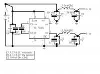
I haven't tried fast charging them as yet as I am not in possession of a suitable charger. I have however purchased a MAX712 fast charger controller and along with a few external components allows for the construction of a fairly comprehensive charger for up to 12 cell batteries. ( there are vways of extended that further, but I have no need for that. I intend to use a set of 10 Cells to provide a nominal supply of 12 volts to feed into my DC-DC converter for the amplifier. I am enjoying this temporary detour from the CCS project, though have every intention of returning to it at a later date.
If anyone living in the UK is interested in them, they are branded as "Fusiomax" NiMH batteries and are sold in poundland stores.
I haven't tried fast charging them as yet as I am not in possession of a suitable charger. I have however purchased a MAX712 fast charger controller and along with a few external components allows for the construction of a fairly comprehensive charger for up to 12 cell batteries. ( there are vways of extended that further, but I have no need for that. I intend to use a set of 10 Cells to provide a nominal supply of 12 volts to feed into my DC-DC converter for the amplifier. I am enjoying this temporary detour from the CCS project, though have every intention of returning to it at a later date.
- Status
- This old topic is closed. If you want to reopen this topic, contact a moderator using the "Report Post" button.
- Home
- Amplifiers
- Solid State
- How do you calculate impedance of a current source?