upgrading the opamps in this DIY kit Velleman k4010 k4020
Dear,
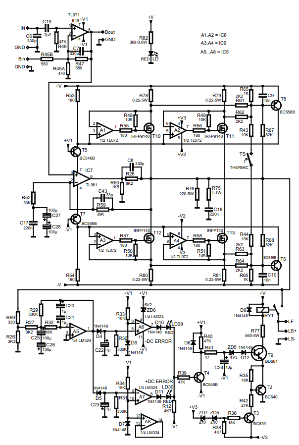
I repared a given (broken) amplifier from Velleman. It works well now and has a lot of power with the IRFP's. But when you look at the schematic, there are a lot of old opamps used. My question is if I can safely change the following opamps to:
TL071 --> OPA134
TL072 --> OPA2134
TL061 --> 'no idea...it has a low current bias?)
I like the "sound" of an opa2134 compared to that one of a NE5532 (both are nice opamps).
Can someone help me by inspecting the circuit and tell me if it is safe to do this simple modification?
Thank you all!
Dear,
I repared a given (broken) amplifier from Velleman. It works well now and has a lot of power with the IRFP's. But when you look at the schematic, there are a lot of old opamps used. My question is if I can safely change the following opamps to:
TL071 --> OPA134
TL072 --> OPA2134
TL061 --> 'no idea...it has a low current bias?)
I like the "sound" of an opa2134 compared to that one of a NE5532 (both are nice opamps).
Can someone help me by inspecting the circuit and tell me if it is safe to do this simple modification?
Thank you all!
Last edited:
I'd be very careful when replacing opamps in a tricked-out piece of kit such as this. Not only because of stability concerns (no output inductor? hmm...), but also because IC7 idle current directly influences MOSFET bias and hence quiescent current!
The only one that should swap out without much issue is IC6, the stock part not being a good fit (TL07x does not particularly enjoy driving low impedance). A local 100n-4µ7 decoupling cap across the supplies may be appreciated, but other than that I could even see an NE5534 working well there (note: include ~22 pF compensation capacitor as per datasheet, OnSemi or Fairchild part preferred since TI has high Ib). Offset should not be amplified further, if I get this correctly. Otherwise you could still use LME49870 (single version of the '49860 - you need the higher voltage version for +/-18 V supplies). OPA134 ought to work quite well, too, even if a '5534 still makes a better load driver. There would have been a better choice even among '70s-vintage FET input parts - the LF356 (a bit slow, but a good load driver for its day).
IC7 must be a low-power part in order to keep quiescent current in check. You could try TLE2061 (note that max Iq is 50% higher). Definitely use a dim bulb tester and keep a scope handy though.
As for the TL072s... their influence shouldn't be that big to begin with. I imagine that since we're in nested feedback here, the simpler the compensation the better. Should be a relatively straightforward part. Maybe not so much a '5532 with its nested feedback, rather some 4558 derivative ('4580?). I have absolutely no idea where the OPA213x ranks in that regard. Again, dim bulb tester, scope.
try to remove C6 330 pF the sound will be improved, simple an effective.
That is NOT helpful advice for a beginner! Nor is it a very good design

The effect of C6, high frequency roll-off and RF suppression depends most of all on the output impedance of the source. A low source Z and C6 will do little or nothing. A high source Z and C6 will kill the treble.
The truth will be somewhere in between, but "removing C6 gives better sound"" is meaningless twaddle unless there is some understanding of the circuit!
seems like adjusting R53 (etc.) ought to adjust the quiescent current, with another opamp in the hole. I'm assuming that T8 & T6 play a role in the DC offset and the bias setting... that bears a bit more of a look see.
this driver section appears to be similar to an app note from National or Signetics (don't recall) that used the PS pins and a load on the output pin in a similar way.
I'm guessing that T11 and T13 are actually connected to the speaker out?
And what is "THERMIC/TS"??
Replacing C27/28 with a film cap would improve the sound, imo.
Removing the HF rolloff/compensation (C8) cap is an invitation for instability.
I think it is a neat design!
seems like adjusting R53 (etc.) ought to adjust the quiescent current, with another opamp in the hole. I'm assuming that T8 & T6 play a role in the DC offset and the bias setting... that bears a bit more of a look see.
this driver section appears to be similar to an app note from National or Signetics (don't recall) that used the PS pins and a load on the output pin in a similar way.
I'm guessing that T11 and T13 are actually connected to the speaker out?
And what is "THERMIC/TS"??
Replacing C27/28 with a film cap would improve the sound, imo.
Removing the HF rolloff/compensation (C8) cap is an invitation for instability.
I think it is a neat design!
I don't think T11 and T13 are directly connected to speaker out. LS as the speaker output.
The thermic/ts is a thermal switch connected to the heatsink.
The preamp coupled with this power amp is a DCB1 (low output Z)..so i think I just gonna leave C6 in place.
So instead of C27/C28 --> just 1 film cap? what value can be used than ?
greetings,
Steven
Last edited:
That cap sets a LF rolloff point. At freqs that are low enough the cap looks like it is a very high Z, so whatever signal is at the input of the opamp is "100%" that making it more or less unity gain. At higher freqs the gain is set by R59 and R52.
They make small low voltage mylar caps that will physically fit...
It's difficult to understand why they would "waste" the second two power mosfets...?
They make small low voltage mylar caps that will physically fit...
It's difficult to understand why they would "waste" the second two power mosfets...?
Is the second pare of mosfets not just a parallel of the first pare?
I'm looking at the scheme and i'm not sure the mosfets are drawn correctly.
I have two NE5534 IC's (I have 2 of these monoblocks) and the 22pF CC for between pin 5 and 8. Gonna solder it directly on top of the ic. I am curruious what this will do with the sound.
If had erlier experiences that a TL072 or TL071 is really not done nowadays. Amazing difference with the NE 5532 / 4. The only problem I got is that the TL061 will be still in the signal path...because it's critical in bias current.
Bear, do you confuse C8 with C6 (both 330pF) ? removing C6 can be done ?
thank you guys for all your' helpfull hands!
Last edited:
C6 = RFI protection and excess HF (ultrasonic) on the input.
C8 = feedback compensation cap.
You can remove C6, but I'd only lessen it unless you know the bandwidth of the amp is low enough, and that you have no strong AM radio stations or other RFI sources that might get amplified if applied to the input. A series inductance would do the same job, fwiw.
Usually the 5534 opamps will sound a bit "tighter" and "harder" than the TL0 opamps. The TL0 are JFET input.
With some experimentation the newer super ultra low distortion opamps could be used.
Certainly they can be put in the first position.
_-_-
C6 = RFI protection and excess HF (ultrasonic) on the input.
C8 = feedback compensation cap.
You can remove C6, but I'd only lessen it unless you know the bandwidth of the amp is low enough, and that you have no strong AM radio stations or other RFI sources that might get amplified if applied to the input. A series inductance would do the same job, fwiw.
Usually the 5534 opamps will sound a bit "tighter" and "harder" than the TL0 opamps. The TL0 are JFET input.
With some experimentation the newer super ultra low distortion opamps could be used.
Certainly they can be put in the first position.
_-_-
Thank you Bear;
The ne5532 / 4 sound very natural and good. In a phono pre I played with the opa2134 also...also JFET input....and indeed that sounds different (also good)
- Status
- This old topic is closed. If you want to reopen this topic, contact a moderator using the "Report Post" button.
- Home
- Amplifiers
- Solid State
- upgrading the opamps in this DIY kit