Hi Frederico, All,
I've cross-checked with AIMSpice. Results are in agreement with Micro-Cap 7 results, i.e. not satisfactory.
Actually looking at the diagnostics, I can see that about half of the parameters are rejected as unknown. So there's no big guess, what 's happening.
Seems LTSpice is state-of-the-art regarding JFET modeling.
Regards,
Peter Jacobi
pjacobi said:.model 2sk170 NJF(Beta=51.76m Rs=8.008 Rd=8.008 Betatce=-.5 Lambda=11.22m
+ Vto=-.5275 Vtotc=-2.5m Cgd=18.28p M=.3367 Pb=.3905 Fc=.5
+ Cgs=20.07p Isr=112.8p Nr=2 Is=11.28p N=1 Xti=3 Alpha=10u Vk=100
+ Kf=92.85E-18 Af=1)
fscarpa58 said:using Micro-Cap 7
you can obtain
the 3 curves of post #60
with any generic njfet model
by putting IS= 1n , 15 p, 10F
respectively for curves 1,2 and 3.
I think gate current is not well
modelled here
I am disappointed
I've cross-checked with AIMSpice. Results are in agreement with Micro-Cap 7 results, i.e. not satisfactory.
Actually looking at the diagnostics, I can see that about half of the parameters are rejected as unknown. So there's no big guess, what 's happening.
Seems LTSpice is state-of-the-art regarding JFET modeling.
Regards,
Peter Jacobi
Hi Christer,
If you operate a x1 stage at +-24V, and you don't do something really strange, it's nearly impossible to get worse than -150dB for 100mV pk signals.
O.K. There may be a bareley visible K2 spike. But everything above starts at least with a bonus factor of 1/240 * 1/240 before even taking anything into account that makes the circuit well-behaved.
Regards,
Peter Jacobi
Christer said:For instance, with 10kHz 5V pk input, I got -94dB 2nd order
and -117dB 3rd order. With 100mV pk input I got basically no
visible distorsion above the -155dB noise floor of the FFT.
Those are just simulation figures, but they seem promising.
If you operate a x1 stage at +-24V, and you don't do something really strange, it's nearly impossible to get worse than -150dB for 100mV pk signals.
O.K. There may be a bareley visible K2 spike. But everything above starts at least with a bonus factor of 1/240 * 1/240 before even taking anything into account that makes the circuit well-behaved.
Regards,
Peter Jacobi
Peter,
You started this thread before I made my recent post in the original
thread. As I pointed out there, Spice modelling was not really the
issue, but other people seemed to make it the issue, or assume it
was the issue. As I also said there, the distorsion figures should be
taken with a very large grain of salt. I think we can expect a real
circuit to have at least as much distorsion, but otherwise I am not
sure if we know much. I do think distorsion analyses in Spice can
serve a purpose for comparative purposes of the kind we discussed
in the Diamond buffer thread, but that is an assumption.
Just for the record, I see you put "Borbely FET follower" in the thread
title. Actually, the circuit wasn't one of Borbelys' but rather what I
understand to be John Curls own variant of the White follower.
The riddle of the gate current simulation differences is solved.
It's the JFET impact ionization current, see:
http://www.google.com/search?hl=en&...+impact+ionization+current&btnG=Google+Search
Its modeling appeared first in PSPICE and didn't migrate to all other SPICES.
Reading the name alone, it should best be avoided, I assume. Which correlates with the practitioners' advice seen in the mother thread.
Regards,
Peter Jacobi
Hi Federico, All,
JFETs, the neglected stepchild of SPICE modeling?
Perhaps some advanced MESFET models can be abused for better results, when it is possible to selectively disable the GaAs specific effects.
Anyway, careless parameter extraction is to blame for the huge differences seen in your posts.
Compare these Philips models with the datasheets:
.MODEL BF245A NJF(VTO=-1.7372 BETA=1.16621E-3 BETATCE=-0.5 LAMBDA=1.77211E-2
+ RD=9.01678 RS=9.01678 CGS=2.20000E-12 CGD=2.20000E-12 PB=7.80988E-1 IS=2.91797E-16 XTI=3 AF=1
+ FC=0.5 N=1 NR=2 MFG=PHILIPS)
.MODEL BF245B NJF(VTO=-2.3085 BETA=1.09045E-3 BETATCE=-0.5 LAMBDA=2.31754E-2
+ RD=7.77648 RS=7.77648 CGS=2.00000E-12 CGD=2.20000E-12 PB=9.91494E-1 IS=2.59121E-16 XTI=3 AF=1
+ FC=0.5 N=1 NR=2 MFG=PHILIPS)
.MODEL BF245C NJF(VTO=-5.0014 BETA=5.43157E-4 BETATCE=-0.5 LAMBDA=2.71505E-2
+ RD=1.20869E1 RS=1.20869E1 CGS=2.00000E-12 CGD=2.00000E-12 PB=1.24659 IS=3.64346E-16 XTI=3 AF=1
+ FC=0.5 N=1 NR=2 MFG=PHILIPS)
This almost makes sense, doesn't it? Add impact ionization current to prevent designers setting Vds too high, and the models would be good enough for most simulations.
Compare with power BJTs. Almost no models implement quasi-saturation. Didn't stop us from using them. Hexfets? If used in class B amplifiers, devices spend signifant part of the cycle in weak inversion, but you'll find models which doesn't model diffusion current at all!
Regards,
Peter Jacobi
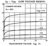
fscarpa58 said:[...]
However I think that static curves of
ID versus VDS are more important in
distortion analysis. look at the difference
between M-Cap and the Toshiba sheets
[...]
JFETs, the neglected stepchild of SPICE modeling?
Perhaps some advanced MESFET models can be abused for better results, when it is possible to selectively disable the GaAs specific effects.
Anyway, careless parameter extraction is to blame for the huge differences seen in your posts.
Compare these Philips models with the datasheets:
.MODEL BF245A NJF(VTO=-1.7372 BETA=1.16621E-3 BETATCE=-0.5 LAMBDA=1.77211E-2
+ RD=9.01678 RS=9.01678 CGS=2.20000E-12 CGD=2.20000E-12 PB=7.80988E-1 IS=2.91797E-16 XTI=3 AF=1
+ FC=0.5 N=1 NR=2 MFG=PHILIPS)
.MODEL BF245B NJF(VTO=-2.3085 BETA=1.09045E-3 BETATCE=-0.5 LAMBDA=2.31754E-2
+ RD=7.77648 RS=7.77648 CGS=2.00000E-12 CGD=2.20000E-12 PB=9.91494E-1 IS=2.59121E-16 XTI=3 AF=1
+ FC=0.5 N=1 NR=2 MFG=PHILIPS)
.MODEL BF245C NJF(VTO=-5.0014 BETA=5.43157E-4 BETATCE=-0.5 LAMBDA=2.71505E-2
+ RD=1.20869E1 RS=1.20869E1 CGS=2.00000E-12 CGD=2.00000E-12 PB=1.24659 IS=3.64346E-16 XTI=3 AF=1
+ FC=0.5 N=1 NR=2 MFG=PHILIPS)
This almost makes sense, doesn't it? Add impact ionization current to prevent designers setting Vds too high, and the models would be good enough for most simulations.
Compare with power BJTs. Almost no models implement quasi-saturation. Didn't stop us from using them. Hexfets? If used in class B amplifiers, devices spend signifant part of the cycle in weak inversion, but you'll find models which doesn't model diffusion current at all!
Regards,
Peter Jacobi
Peter,
Although I haven't really investigated that many manufacturers
models, my impression is that also BJT model are often mediocre
at best when compared to the datasheets. I spent quite some
time about a year ago trying to DIY models for some BJTs I couldn't
find any Spice models for. I tried to really understand the Spice
equations as described in my, admittely somewhat old, semiconductor
physics book, and figure out both by theoretical thinking and by
epxeriments with tweaking parameters how to create a good model.
It may be my due to limitations in my understanding, but I really
couldn't find any way either in theory or in practice to come up
with a suffciently good general-purpose model of any of these
BJTs. I ended up having to make a compromise fitting neither of
the most importand diagrams really well nor any of them
really bad. Some improvement could be achieved if tailoring the models
to the intended operating conditions, but some parameters seem
still impossible to model well. I couldn't find any way to get the
high injection effects (beta droop) as serious as often indicated
in the datasheets. There might be further parameters in some
modern Spice implementations that improve on this, but if so
they seem not to be standard Spice 3.
Hi Christer,
You've done something I always planned to but it never got the top of priority list. As always I'll comment anyway.
- Not perfectly modeling beta droop shouldn't be a problem, as it is easy to operate all your devices below the F(transit) peak (in DIY, as you don't have to optimize your part cost)
- You have IKF, base and collector resistances as the most straightforward ingredients to model beta droop. Want to share one your attempts? I'll have a look on it.
- OTOH you can't avoid quasi-saturation, I'll consider this much more problematic
- If you have time and a C compiler at hand, you can experiment with the Philips MEXTRAM model for BJT:
http://www.semiconductors.philips.com/Philips_Models/bipolar/mextram/
Regards,
Peter Jacobi
Christer said:[...] my impression is that also BJT model are often mediocre
at best when compared to the datasheets. [...] but I really
couldn't find any way either in theory or in practice to come up
with a suffciently good general-purpose model of any of these
BJTs. [...] I couldn't find any way to get the
high injection effects (beta droop) as serious as often indicated
in the datasheets.[...]
You've done something I always planned to but it never got the top of priority list. As always I'll comment anyway.
- Not perfectly modeling beta droop shouldn't be a problem, as it is easy to operate all your devices below the F(transit) peak (in DIY, as you don't have to optimize your part cost)
- You have IKF, base and collector resistances as the most straightforward ingredients to model beta droop. Want to share one your attempts? I'll have a look on it.
- OTOH you can't avoid quasi-saturation, I'll consider this much more problematic
- If you have time and a C compiler at hand, you can experiment with the Philips MEXTRAM model for BJT:
http://www.semiconductors.philips.com/Philips_Models/bipolar/mextram/
Regards,
Peter Jacobi
pjacobi said:
You've done something I always planned to but it never got the top of priority list. As always I'll comment anyway.
- Not perfectly modeling beta droop shouldn't be a problem, as it is easy to operate all your devices below the F(transit) peak (in DIY, as you don't have to optimize your part cost)
- You have IKF, base and collector resistances as the most straightforward ingredients to model beta droop. Want to share one your attempts? I'll have a look on it.
I ended up with the following models for some drivers. I am not
saying they are the best compromises, but I found I eventually
had to settle on something. Further tweaking of the models may
be worthwhile for a particular usage I suppose. I suppose some
parameters may be way off, but the main purpose was to try
mimicing the datasheets in an acceptable way, so the end results
was what mattered most to me.
.model 2SD669 NPN (IS=5p NF=1 BF=250 ISE=5p NE=1.5 IKF=3 VAF=150 RB=1 RC=0.25 RE=0.25 TF=1.14ns CJC=50p )
.model 2SB649 PNP (IS=5p NF=1 BF=250 ISE=10p NE=1.5 IKF=3 VAF=75 RB=1 RC=0.25 RE=0.25 TF=1.14ns CJC=50p )
.model 2SC4793 NPN (IS=0.1p BF=130 NF=1 ISE=0.1p RB=1 RE=0.1 RC=0.2 VAF=500 IKF=3 TF=1.6ns CJC=100p )
.model 2SA1837 PNP (IS=0.1p BF=130 NF=1 ISE=0.1p RB=1 RE=0.1 RC=0.2 VAF=500 IKF=3 TF=2.28n CJC=150p )
I know there is at least one book about making Spice models, but
I haven't read it, just worked from the theory in my old course
book.
Christer said:
I know there is at least one book about making Spice models, but
I haven't read it, just worked from the theory in my old course
book.
Christer,
Here's the link to Massobrio and Antognetti.
http://www.amazon.com/exec/obidos/t...f=sr_1_1/002-3868523-8604813?v=glance&s=books
The whole issue with models can get quite discouraging. I recently worked with a guy that was responsible for the code of a harmonic balance simulator. It can do intermods with a large number of tones. He was extending the software to use SPICE models for devices in addition to the native models for the simulator. The harmonic balance simulator is very sensitive to discontinuities in the equations for the device characteristics. It fails to converge in the presence of certain types of discontinuities. He had to completely abandon the use of level 1, level 2 and level 3 MOSFET SPICE models because of convergence problems due to discontinuities. So I suspect that SPICE distortion simulations with these devices will indicate a lot of high-order harmonics that are just artifacts of the discontinuities in the models.
In looking at distortion simulations for a power amp using MOSFET drivers and output stage, I was disappointed to find out that the level 1, 2 and 3 MOSFET models model the gate-to-drain capacitance as constant with gate-to-drain voltage. This is completely wrong for vertical MOSFETs. So I'm looking at trying to fit the LTSpice VDMOS model to the data sheet parameters. I'd like to find out how much the nonlinear gate-drain capacitance of the MOSFET drivers affects the distortion, and what kind of improvement I might expect by bootstrapping the drain to the level-shifted output voltage a la Halcro. But this is very time-consuming! Right now, other responsibilities prevent me from taking the time to do this, but I will get there eventually.
It is the model. SwCAD shows the similar curves. But no problem, keep the Vds constant in your circuit, and you have the model.john curl said:The Mcap curve sucks! It is not reality.
")
Pedja
Attachments
Hi Pedja, All,
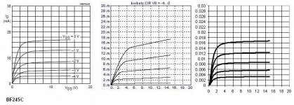
Three graphs, three problems.
a) IGSX / VDS => SPICE version problem, only some SPICEs model the impact ionization current at all.
b) ID / VDS => Sloppy models, compare the BF245 models.
c) ID / VGS => Bad theory, this looks too good, as it looks rather quadratic. Despite endless repititions this ain't right. Compare formulas 3-11 and 3-12 in Massobrio/Antognetti. And the datasheet curves.
Regards,
Peter Jacobi
Pedja said:It is the model. SwCAD shows the similar curves.
[...]
Three graphs, three problems.
a) IGSX / VDS => SPICE version problem, only some SPICEs model the impact ionization current at all.
b) ID / VDS => Sloppy models, compare the BF245 models.
c) ID / VGS => Bad theory, this looks too good, as it looks rather quadratic. Despite endless repititions this ain't right. Compare formulas 3-11 and 3-12 in Massobrio/Antognetti. And the datasheet curves.
Regards,
Peter Jacobi
Anyway, careless parameter extraction is to blame for the huge differences seen in your posts.
Compare these Philips models with the datasheets:
I did it.
Look at the following 3 sets of curves referring to BF245C
1) from philips
2) from Micro-Cap
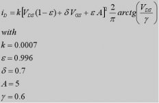
3) drawn using a pentode model with parameter fitting
made manually in five (5) minutes
Yes, it is not perfect, but with more time I am sure to
obtain near perfect curves.
I think spice model developers
have to work more and better.
Any comment ?
Federico
Attachments
Hi Federico,
Very impressive comparison!
Will you make this available? Which pentode model are you using?
IMHO there is a problem with the monolithic architecture of SPICE. Either you have to recompile the whole mess to add a new model or you are confined to what's possible with subcircuit models.
If it would be possible to add experimental models as seperately compiled modules (DLLs) or if a reasonable fully featured programming language interpreter would be included (Javascript, Python, whatever), it would be much easier to tinker around and try things and share improved models.
The ngSpice project had this on its agenda, but it seems to be abonded: http://geda.seul.org/tools/ngspice/
Regards,
Peter Jacobi
Very impressive comparison!
fscarpa58 said:[...]
3) drawn using a pentode model with parameter fitting
made manually in five (5) minutes
[...]
Will you make this available? Which pentode model are you using?
fscarpa58 said:I think spice model developers
have to work more and better.
IMHO there is a problem with the monolithic architecture of SPICE. Either you have to recompile the whole mess to add a new model or you are confined to what's possible with subcircuit models.
If it would be possible to add experimental models as seperately compiled modules (DLLs) or if a reasonable fully featured programming language interpreter would be included (Javascript, Python, whatever), it would be much easier to tinker around and try things and share improved models.
The ngSpice project had this on its agenda, but it seems to be abonded: http://geda.seul.org/tools/ngspice/
Regards,
Peter Jacobi
- Status
- This old topic is closed. If you want to reopen this topic, contact a moderator using the "Report Post" button.
- Home
- Amplifiers
- Solid State
- Borbely Fet Follower SPICE modeling