- Hi all.
I am using LM311 comparator to design a speaker protection circuit. I read quite a few data sheet of LM311. Seems like it's such an old IC that they assume people know the IC already. I happen to be a first time user and I am not sure I design it right. Mainly strobe pin #6. From reading, it seems like if I use a transistor to pull it down, the output transistor turns off regardless and become open circuit pulled up by the pull up resistor. Also the output transistor how I can use it off ground. Anyone that familiar with the LM311, please confirm I designed the circuit correctly.
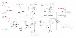
Also, this is a speaker protection circuit for SS amp that can drive a DC voltage if something gone wrong. This circuit will:
1) monitor the output by using a low pass filter to filter out the audio frequency, only the very very low frequency or DC passes through. Two window comparators using LM311(U1 & U3, U2 & U4) are used to monitor the DC and turn off the transistor if over 0.7V DC is detected.
2) monitor circuit to monitor +/-24V supply (R3, D3 and relay S1). If total voltage drop by say 5V, the relay opens.
3) Power on delay (Q1 C15). The drain of the Q1 connects to pin 6 of all the comparators. when Q1 is on and pull all the pin 6 to ground, the LM311 turns off.
The /OUTPUT EN are use to turn on the speaker output relay when it is pulled to ground.
I am connecting the two LM311 output transistors in series with the relay contact, so if anyone opens, the chain opens and loss the ground, the speaker relay will be turned off. Only if both NPN output transistor of LM311 and the relay are on, then the /OUTPUT EN will be low to turn on the speaker relay. Please confirm that I am doing everything correctly.
Thanks
Alan
Attachments
First of all, you do not need two channel circuit for stereo. After all, if one of the amp speaker is disabled, you do not want to listen to the other channel.
I don't see any low pass filter for detecting DC.
Gajanan Phadte
Edit:Even if you are disabling both the relays, you don't need double the circuit.
I don't see any low pass filter for detecting DC.
Gajanan Phadte
Edit:Even if you are disabling both the relays, you don't need double the circuit.
Last edited:
I don't see any low pass filter for detecting DC.
Gajanan Phadte
Edit:Even if you are disabling both the relays, you don't need double the circuit.
R4+R5+C5
Sajti
First of all, you do not need two channel circuit for stereo. After all, if one of the amp speaker is disabled, you do not want to listen to the other channel.
I don't see any low pass filter for detecting DC.
Maybe I can sum the two output into one set of window detector.
thank
Elegant approach - using separate RC filter for each channel and then using two small signal diodes (e.g. 1N4148) per channel for connecting those filters to the same window comparator. This way you can connect as many channels if you like without interference between them. Any channel, introducing DC offset outside the window, will trip the protection.
In this case - compare to "Ground". 0.7V will fall on those diodes.
Cheers,
Valery
In this case - compare to "Ground". 0.7V will fall on those diodes.
Cheers,
Valery
Attachments
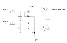
ThanksElegant approach - using separate RC filter for each channel and then using two small signal diodes (e.g. 1N4148) per channel for connecting those filters to the same window comparator. This way you can connect as many channels if you like without interference between them. Any channel, introducing DC offset outside the window, will trip the protection.
In this case - compare to "Ground". 0.7V will fall on those diodes.
Cheers,
Valery
Good idea.


How about the way use the pin #6 for power on delay?
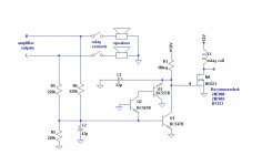
I got a suggestion from Physics Forums that actually simpler and seems like it works for everything I want.
C1 is the start up delay, C2 is the low pass filter. If +12V failed, the MOSFET loss gate drive. If -12V failed, the relay loss power.
This got to be the simplest circuit I've seen.
C1 is the start up delay, C2 is the low pass filter. If +12V failed, the MOSFET loss gate drive. If -12V failed, the relay loss power.
This got to be the simplest circuit I've seen.
Attachments
Last edited:
I got a suggestion from Physics Forums that actually simpler and seems like it works for everything I want.
C1 is the start up delay, C2 is the low pass filter. If +12V failed, the MOSFET loss gate drive. If -12V failed, the relay loss power.
This got to be the simplest circuit I've seen.
Polarised cap C2 has a 50% chance of getting a reverse bias after an output stage blowup, so may fail.
Have you any pcb for this?I've used this one a couple of times before. Works 100%
Other than there is no monitor for -24V, looks good. But I guess if the -24V failed, the output will have DC and will shut off.I've used this one a couple of times before. Works 100%
Alan, post7.
the delay time constant is quite long.
1M & 22uF gives 22s. This is the time for the C1 voltage to rise to ~60% of the supply voltage. The FET will probably trigger well before the 22s is reached, but how early depends very much on the Vgs of M1. If due to triggering of M1 and the sudden increase in current, the supply voltage could drop and the gate may untrigger.
The LF filter detecting DC offset also has a very long time constant.
Removing R6 for first stage (simple) analysis gives 10.3s for 220k and 47uF.
Adding in R5 increases the delay significantly, while DC offset is still increasing. The DC offset could be very large by the time that the relay contacts start to open. The current could now burn the contacts and maybe weld them closed.
I have two suggestions.
Use a 555 for each of your timing sequences ( the soft start as well). They are reliable and cheap.
I use a 3u3F plastic film for C2. Avoids all problems of reverse biasing of an electrolytic.
I omit R5 to give a fast voltage rise on C2.
But there is a very small range of input frequency where the detector starts to oscillate, in simulation. This oscillation usually cuts off the relay and the delay prevents it coming back on immediately. But I have doubts about how well I have tested this. It always seems to work on the bench.
The other thing I have found is that a small offset takes a long time for the detector to react and cut off the relay. A medium offset cuts off the relay fairly quickly, if you get the components values about right.
A very high offset cut off the relay VERY fast.
This is something I doubt the comparator style can do without a lot of complication. I suspect a PIC controller cannot do this either.
Last edited:
Sorry Thimos, I made the board which I copied from Quasi's design. I have used the layout of the nmos 350.
https://sites.google.com/site/quasisdiyaudiosite/nmos-series/nmos350-500
https://sites.google.com/site/quasisdiyaudiosite/nmos-series/nmos350-500
Alan, post7.
the delay time constant is quite long.
1M & 22uF gives 22s. This is the time for the C1 voltage to rise to ~60% of the supply voltage. The FET will probably trigger well before the 22s is reached, but how early depends very much on the Vgs of M1. If due to triggering of M1 and the sudden increase in current, the supply voltage could drop and the gate may untrigger.
The LF filter detecting DC offset also has a very long time constant.
Removing R6 for first stage (simple) analysis gives 10.3s for 220k and 47uF.
Adding in R5 increases the delay significantly, while DC offset is still increasing. The DC offset could be very large by the time that the relay contacts start to open. The current could now burn the contacts and maybe weld them closed.
I have two suggestions.
Use a 555 for each of your timing sequences ( the soft start as well). They are reliable and cheap.
I use a 3u3F plastic film for C2. Avoids all problems of reverse biasing of an electrolytic.
I omit R5 to give a fast voltage rise on C2.
But there is a very small range of input frequency where the detector starts to oscillate, in simulation. This oscillation usually cuts off the relay and the delay prevents it coming back on immediately. But I have doubts about how well I have tested this. It always seems to work on the bench.
The other thing I have found is that a small offset takes a long time for the detector to react and cut off the relay. A medium offset cuts off the relay fairly quickly, if you get the components values about right.
A very high offset cut off the relay VERY fast.
This is something I doubt the comparator style can do without a lot of complication. I suspect a PIC controller cannot do this either.
That's how it is, a simple idea turn out not to be that simple when you start to implement into real circuit. I looked at all the ideas so far, they all have potential issues. I am going back to my original schematic, using VZAICHENKO's idea in post #5 to eliminate half the circuit. There is still a small problem on his idea, the two inputs of the LM311 are sitting on ground level during normal operation, that will cause oscillation at the output and click the relay. I have to put in some bias also.
I don't follow your description on the short coming of the comparator circuit. If the output is within the window ( +/-0.7V) the output relay will be on. When output is beyond the window, the relay turns off. At the edge of the window, it's not important how it behaves as it won't burn the speaker. The chattering should be noticeable and I would go and check!!!
BTW, if you read my final schematic in my OPS thread, I use SS relay on the OPS board, there will be no contact to melt. The relay is 4 N MOSFET to form two parallel switch to obtain very low resistance. The boards were shipped out on 3/14, so I'll be receiving them soon. I just ordered all the parts already. The whole thing is about $1000!!!. But I did ordered enough transistors to build 5 amplifiers!!! I want to hand pick power transistors and input differential transistors.
Man!!! I ordered 45 each of the MJL3281 and 1302, 100 each of the BC546, BC556 just to hand pick, the cost really adds up.
Last edited:
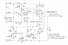
I updated the design. I am still using LM311. The difference from the original design are:
1) Removing one of the two window comparator consists of two LM311 and sum both outputs of the amp into one window comparator.
2) Remove the +/-24V supply monitoring that get rid of the relay. As long as the output is close to zero, whether the supply collapsed is irrelevant, the sound will tell me it's wrong already.
3) I remove the MOSFET.
I still have not heard from anyone whether I am correct in using pin #6 ( Strobe) of the LM311. I use it as power up delay. The capacitor C15 hold pin #6 low for a little bit to keep the speaker relay from turning on for a few seconds.
The circuit is still more complicate than the transistor circuits, but I like the more defined operation. I don't want to deal with beta of the transistor.
Thanks
Attachments
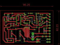
This is my work in progress pcb of Hafler DH500 SP protection circuit with some additions for power. I use CD4541 timer for power on delay with its own transformer. The timer has auto reset on power failure and this is what I use it for. I have been using it for couple of years but it is assembled on protoboard.
For added benefit, the low pass capacitors should be polycarbonate type.
Gajanan Phadte
For added benefit, the low pass capacitors should be polycarbonate type.
Gajanan Phadte
Attachments
I did not think I made a comment about a "short" at the comparator?I don't follow your description on the short coming of the comparator circuit.
What comment/part are you referring to?
If you use a bigger value i.e. 22 microfarad for the low pass, it will be costly as you have to use a bipolar cap. Instead, you can use a bigger R and a smaller cap which will be a film type below one microfarad.
Gajanan Phadte
Many times tested values for the input filter, used in our "21-st century protection" - 47K and two 100uF caps (in series, back-to-back).
I am using protection circuit from post #7 for past couple of yeares. The capacitor in RC filter I have used 10uf and removed the parallel 220kr resistor next to it. The circuit is very fast and never failed me down. Just think one more time how you are going to blow the capacitor in RC filter, threw 220kr? Not possible.
- Status
- Not open for further replies.
- Home
- Amplifiers
- Solid State
- Speaker protection using LM311