I have a Yamaha RX1130 that was snagged at the dump about 4 yrs ago. First component that I repaired, way before what I know now but ended up replacing about 7 components, one output device, on the amp board. Did get both channels operating. Listened to it for several months giving it some hot suppers before I finally realized it was in mono? Now remember this was way before any learning that I have done so back then I brought it to a couple shops that wanted nothing to do with it which now I understand. But I could put that back on the bench and see if I can determine what is going on. I purchased the repair manual back then for the shops to use.
What's happening is when the balance knob is turned to 1 channel the volume level decreases a bit on both channels and audio with equal volume level comes out of both channels. Wouldn't that mean somewhere upstream the input signals are mixing?
Let me answer that. I just went downstairs and pulled the jacks between the amp and preamp. Proceeded to hook up a portable CD player putting the signals straight into the amp. both channels operating but when I pull either of the input signals sound still comes from both speakers. in my simple mind that seems to be a positive because it means that the signals are not mixing somewhere upstream from the amplifier section that could be difficult for me. It would seem all I have to do is troubleshoot the power amplifier board.
Attachments
visually R200 on emitter circuit of Q138 looks smoked. Measures open.
checked TP- /TP+ should measure 6-8mV measure 0mV probably no surprise if R200 is open. Is this the bias current? Also measured DC offset right channel 83mV and the left channel measured 90mV. See attached color coded amp schematic. Attempted a measurement of R200 insitu and it appears to be open. Really ticks me off that neither of the attempts to get it looked at was the basic bias and DC offset measurements taken. The measurement at TP- / TP+ right channel might have been a big flag. The place in Cambridge Boston, Audio Lab, is supposed to be a reputable place?
checked TP- /TP+ should measure 6-8mV measure 0mV probably no surprise if R200 is open. Is this the bias current? Also measured DC offset right channel 83mV and the left channel measured 90mV. See attached color coded amp schematic. Attempted a measurement of R200 insitu and it appears to be open. Really ticks me off that neither of the attempts to get it looked at was the basic bias and DC offset measurements taken. The measurement at TP- / TP+ right channel might have been a big flag. The place in Cambridge Boston, Audio Lab, is supposed to be a reputable place?
I would recommend not messing with the fonts so much. It just so happens that - *gasp* - people may actually want to be able to read what you write without having to crawl into the screen.
Full quote with the offending tags removed:
As for your problem, if the two channels mix like that, there are only two things that could be wrong:
1. Signals are shorted together somewhere.
2. There is a bad ground connection somewhere, up to and including the speaker terminals and power supply section. Ribbon cables and such may be worth checking, though with some bad luck it could be a cracked PCB as well. Make sure there is continuity between speaker return and transformer secondary center tap (or between the big filter capacitors). Same goes for the input side.
I'll go have a look at the docs now...
R200 is not essential for the function of the amplifier, but it being smoked indicates that significant current must have flown through the outputs, in line with what you state. Have you found any burnt traces? Is Q140 still alive and kicking (or replaced)?
Full quote with the offending tags removed:
I have a Yamaha RX1130 that was snagged at the dump about 4 yrs ago. First component that I repaired, way before what I know now but ended up replacing about 7 components, one output device, on the amp board. Did get both channels operating. Listened to it for several months giving it some hot suppers before I finally realized it was in mono? Now remember this was way before any learning that I have done so back then I brought it to a couple shops that wanted nothing to do with it which now I understand. But I could put that back on the bench and see if I can determine what is going on. I purchased the repair manual back then for the shops to use.
What's happening is when the balance knob is turned to 1 channel the volume level decreases a bit on both channels and audio with equal volume level comes out of both channels. Wouldn't that mean somewhere upstream the input signals are mixing?
Let me answer that. I just went downstairs and pulled the jacks between the amp and preamp. Proceeded to hook up a portable CD player putting the signals straight into the amp. both channels operating but when I pull either of the input signals sound still comes from both speakers. in my simple mind that seems to be a positive because it means that the signals are not mixing somewhere upstream from the amplifier section that could be difficult for me. It would seem all I have to do is troubleshoot the power amplifier board.
visually R200 on emitter circuit of Q138 looks smoked. Measures open.
checked TP- /TP+ should measure 6-8mV measure 0mV probably no surprise if R200 is open. Is this the bias current? Also measured DC offset right channel 83mV and the left channel measured 90mV. See attached color coded amp schematic. Attempted a measurement of R200 insitu and it appears to be open. Really ticks me off that neither of the attempts to get it looked at was the basic bias and DC offset measurements taken. The measurement at TP- / TP+ right channel might have been a big flag. The place in Cambridge Boston, Audio Lab, is supposed to be a reputable place?
As for your problem, if the two channels mix like that, there are only two things that could be wrong:
1. Signals are shorted together somewhere.
2. There is a bad ground connection somewhere, up to and including the speaker terminals and power supply section. Ribbon cables and such may be worth checking, though with some bad luck it could be a cracked PCB as well. Make sure there is continuity between speaker return and transformer secondary center tap (or between the big filter capacitors). Same goes for the input side.
I'll go have a look at the docs now...
R200 is not essential for the function of the amplifier, but it being smoked indicates that significant current must have flown through the outputs, in line with what you state. Have you found any burnt traces? Is Q140 still alive and kicking (or replaced)?
Last edited:
decided to look at the first two transistors that the signals hit Q105 and Q106 muting function. Is the schematic wrong or is the emitter of Q105 supposed to be connected to the collector of Q106. On the board it appears that their collectors are connected to E.
Attachments
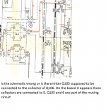
Probably a misprint, though I'd guess with muting transistors it doesn't matter so much anyway (they need to have high reverse beta).decided to look at the first two transistors that the signals hit Q105 and Q106 muting function. Is the schematic wrong or is the emitter of Q105 supposed to be connected to the collector of Q106. On the board it appears that their collectors are connected to E.
Updated my previous reply.
R200 is not essential for the function of the amplifier, but it being smoked indicates that significant current must have flown through the outputs, in line with what you state. Have you found any burnt traces?
I have at this point looked the entire board over using magnification. I don't believe there are any burnt traces. What caused the original failure was a liquid short between J213 and J249. The original repair effort was years ago but I do remember that the ribbon cable from the predriver board was removed. I remember trying to get it reconnected, it was not for the light hearted.
Last edited by a moderator:
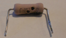
while I was identifying the jumpers that had shorted decided to check emitter resistor values. Measure .22 ohms across R182, R184, R186. Measured 10ohms across R188 the emitter resistor for Q138?
will manually ring out the ribbon wire cable removed during the predriver board repairs.
will manually ring out the ribbon wire cable removed during the predriver board repairs.
Q140 measures:
65V on collector should be 71V(rail supply)
0V on base should be 0V
250mV on emitter should be 0V
Because Q140 collector should be at 71V went back to PS.
Measured 45.5Vac across transformer secondary instead of 52.3Vac.
Question is can the transformer secondary be good while something downstream is dragging it down?
Ringing ribbon cable between predriver board 2 and the main board (right channel) resulted in no connection between the negative output from predriver Q130 and the negative output section of the right channel.
It now rings through.
One would assume that where there was no input to negative Q138 (output) and Q134 (output), that these devices would not be outputting to the speaker. Remember that it was negative output Q134 that was replaced originally. Discovered yesterday that the emitter (R188) resistor of its mate Q138 measures 10 ohms should be .22ohms. Also R200 is open and needs replacement.
I believe that powering it up with the negative output of the predriver board now operating could be dangerous? The emitter resistor R188 should be replaced. Probably should use a DLB set up in the event there is a failure in the negative side of right channel output.
Hi Bob,
What you should do is replace all four output transistors, and both driver transistors. If one output failed, the others got stressed for certain. Replace the blown stage, plus one stage back when repairing any amplifier. That can be a real drag it there are 9 outputs in parallel. You would replace 18 outputs and the driver transistors - minimum. In this case you have four outputs that should be considered as failed. They can blow later, or simply misbehave causing you no end of trouble.
If the previous shop only replaced one transistor (roadie or bad shop), chances are they didn't clean the old grease out and use fresh. Insulators are easy to damage and one day the output may contact the heat sink. Fun.
You should also replace the bias transistor and install a new matched pair of transistors for the differential pair. The DC Offset will force one input transistor to break down E-B, damaging it (a soft failure where the part parameters changed but it still works). So do these things in addition to the other dead parts before you "spark it up".
-Chris
Last edited:
Hey Bob,
R200 is part of the over current protection. Absolutely replace that, and also Q140. R184,188 are shot as you found. When R184 & R188 opened / went high is value, the current tried to run through Q140 and R200. R182 and R186 should also be replaced as they are in series between the two output transistors. One sneaky problem is you may have an open or high value for R172 (390 R) between Q130 and Q128. If it goes open you will have high bias, outside the range of adjustment.
-Chris
anatech, All the drivers upstream from the output section were replaced. The output stage of this is two pairs of complimentary 2SA1265/2SC3182. I only replaced one of the 2SA1265. Are you stating to replace all four or just the other 2SA1265?
R172 got replaced.
R172 got replaced.
Last edited:
Hi Bob,
-Chris
Yes, sorry. When one dies, the others were close. They have all been taken beyond their SOA and are no longer trustworthy. Only the weakest link shorted. You could use On Semi MJW0302 and MJW0281. They are fantastic parts. Any of the new MJLxxxx parts are really good. They are also current and have local distribution.Are you stating to replace all four or just the other 2SA1265?
-Chris
Last edited:
Hi Bob,
They are probably close enough. I have seen some pretty darned fine resistor leads on these 1/6 th watt parts. I can't see you having trouble with a 1/4 watt part. Just like I don't stock anything less than 1/4 watt resistors, except with some surface mount resistors.
You should be back in business soon.
-Chris
Okay, removed muting transistors Q105 and Q106. Powered on and exhibiting same symptom. When balance knob is turned right or left both channels on.
Ringed out the right channel ribbon cable between predriver board and the main amp board again. One of the connections was not ringing through again so it was finessed into ringing through again.
While I was ringing the 8 conductor cable I discovered that the +B and -B rails are shorted? Interestingly enough I checked the left channel (left channel required no repair work) and it also rings the +B and -B rails.
Removed C126 due to swelling. It reads 33/50 while the schematic calls out a 10/25. The schematic shows a 33/50 for Canadian models while the US models were supposed to have a 10/25. The Canadian model shows an impedance switch on the back which this doesn't have. I am sure this is a US model.
Can I go ahead and put the 10/25 in?
Also removed and replaced the 0.22ohm emitter resistor. If only this could have been seen from the top side?
Can I go ahead and put the 10/25 in?
Also removed and replaced the 0.22ohm emitter resistor. If only this could have been seen from the top side?
Attachments
- Status
- This old topic is closed. If you want to reopen this topic, contact a moderator using the "Report Post" button.
- Home
- Amplifiers
- Solid State
- Yamaha RX1130 R&L input signals mix in the output section