One way to get the gain correct is to measure it as it stands now with the tone controls centred.
Measure the input to the power amp and its output using a 1kHz sine and calculate the AC gain from these two figures. When you have done that we can derive a suitable feedback network.
Measure the input to the power amp and its output using a 1kHz sine and calculate the AC gain from these two figures. When you have done that we can derive a suitable feedback network.
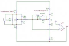
One thing you could do is to put the tone controls at neutral and then measure the voltage across the whole tone stack, for different frequencies (probably is flat).
That gives you an idea about the required impedance that should replace it.
Edit: I now see Mooly had the same idea. And he was first ;-(
Jan
That gives you an idea about the required impedance that should replace it.
Edit: I now see Mooly had the same idea. And he was first ;-(
Jan
")
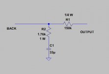
here is a brief discussion on the cap you are asking about: capacitor in parallel with negative feedback resistor
thanks roger .
do you think 10pF will be fine ?
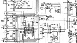
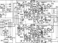
This denon , does not have an preamp stage .
The signal goes strait to power stage , what do you think about this design ?
I have no idea about what value to use for that capacitor and am not able to comment on the amp design. I am not knowledgeable like Mooly, jan.didden, and others here. I posted the link for you because I was aware of that thread and I thought that you may be interested to read it.
The picture that Mooley gave you looks like the NFB loop in several (commercial design) schematics that I have studied. I see that parallel ceramic cap in all of them.
I will be interested to learn from this thread as I have considered doing the same modification to one of my amps.
Last edited:
- Status
- This old topic is closed. If you want to reopen this topic, contact a moderator using the "Report Post" button.
- Home
- Amplifiers
- Solid State
- Need help to cancel tone control in an amplifier