Hi all,
I am currently working on a Marantz PM250 amplifier. It powers up OK and there is DC voltage at the rectifier diodes etc at the correct voltage according to the service manual, but there is no sound from either channel. The output transistors tested OK (de-soldered and tested using a DVM) along with all other transistors on the main board. The only ones I haven't got to yet are the ones on the board behind the tone slider controls.
All resistors check OK too. I have also cleaned the switches with IPA.
The main power supply capacitors also test OK on my ESR meter. I have yet to test the other electro caps on the board. Perhaps this is where the fault may be.
This is very puzzling as so far I have not got to anything that is obviously failed. There is no sign of any charred or burned components on the board either.
Any pointers on what else to look out for (or measure) would be a great help. I am running out of things to test! I don't own an oscilloscope (yet) but I guess it would be very handy right now.
Many thanks,
Luke
Two fundamental tests.
1/ Measure the DC offset of each channels output stage. That's the DC voltage BEFORE any speaker relay. It should be less than 100mv. If the voltage is high then the speaker relay will not be closing (to protect the speakers... don't over ride it)
2/ Measure and confirm the output stage is drawing the correct bias current. This is usually done by measuring the DC voltage across one of the 'emitter resistors' connected to the output transistors. The manual will detail the correct points and value.
I managed to do some tests as follows:
1. DC voltage at speaker terminals = 1.2V (there is no speaker relay inside the amplifier)
2. DC voltage between emitters of main output transistors (should be 11mv on each channel as per manual to give correct bias current) =0 - 0.1mv (It fluctuates very slightly)
I might now decide to test each electro cap for excessive ESR. I really cannot think what else it could be.
Unless it is something on the tone control board.... I forgot to mention that the red lights at the start of the level indicators come on when unit is powered up - no more lights come on due to no sound output.
It is certainly a mystery - one that has eluded me now for about 3 weeks. If I can fix this one then that would be a bloody miracle!
Hi Luke,
Don't bother testing the transistors in the tone section. You are more likely to damage the parts or PCB. Your DC offset should activate the protection circuit. That is why you do not have any bias current in the outputs.
Go over your records again. Make certain you only list facts, no conclusions or guesses, just what you have actually observed. Once that is done your answer is probably in there somewhere. In case this amplifier has a "power good" signal, look for something like a single diode that charges a 1 uF capacitor. That voltage probably leads to a protection network or a microprocessor. That can hole everything in a state that looks like you just turn the amplifier off. With a 'scope you could see if there is a clean DC voltage, or a half wave rectified waveform. Your meter will read this as a DC voltage. You need a 'scope. Do you have the schematic?
Gajanan is checking for a leaky input capacitor, not common these days but still possible.
Good luck, Chris
Are both channels showing the same 1.2 volts DC offset ?
Have you checked both rail fuses are OK ?
Check all the DC voltage supplies are OK. That means around plus 35 and minus 35 volts to the output stage.
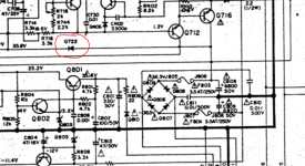
Check that the voltage on the striped end of Q722 (its a diode) is around the same value as the main positive supply.
Have you checked both rail fuses are OK ?
Check all the DC voltage supplies are OK. That means around plus 35 and minus 35 volts to the output stage.
Check that the voltage on the striped end of Q722 (its a diode) is around the same value as the main positive supply.
hi guys - luckily I have this week off from work so more tinkering time! I will do the necessary tests you have very kindly advised me about and report back soon. I also have the schematic handy too in fairly good quality pdf format. I think with people's very handy tips I might well be able to fix this troubled amp! See you in a short while...
Many thanks,
Luke
Many thanks,
Luke
Hi everyone,
After repairing several amps and other hi-fi stuff, nothing yet has stumped me apart from this Marantz! Anyway, here are my findings so far. More to follow tomorrow morning (UK time):
1. Voltage on cathode end of Q722 = 2.66V
2. Some DC voltage readings compared with schematic drawing:
a) Should be +36.5V at Cathode end of Q809, my reading is: 22.5V
b) Should be -36.5V at Anode end of Q806, my reading is -34.2V
c) Should be -28.8V at collector of Q812. My reading is -29.5
d) Should be 36.5V before R801, my reading is 36.3V
e) Should be 13.2V at emitter of Q802, my reading is 3.8V
f) Should be 14V at base of Q802, my reading is 4.4V
3. both rail fuses are OK
4. Right channel at speaker terminals = it climbs from -3.0mv to +3.0mV at speaker terminals. (I measured mV not Volts as I incorrectly stated on my first reply)
Left channel at terminals is same result as right channel.
I'll search for a coupling capacitor and for an input capacitor tomorrow. I am also edging closer to getting a scope! It would make this much easier.
few facts beyond that transistors don't have anodes and cathodes but base collector and emitters (makes other class AB people confused )
The Marantz PM 250 features a mute circuit in the input of the amplifier to provide quite starting that will be ON 21 AND ON 22
Υou may remove those with their anodes and cathodes to bring your amplifier to a no mute state and listen to music from .
Then by looking at the schematic you will understand that this is a simple circuit on the power supply with an RC to produce a start delay
Next to the first facts please add that capacitors inside that old amplifier DO not need checking All small capacitors inside your amp are only good enough to meet the creator ....
With anodic sense of humor
Kind regards
Sakis
The Marantz PM 250 features a mute circuit in the input of the amplifier to provide quite starting that will be ON 21 AND ON 22
Υou may remove those with their anodes and cathodes
to bring your amplifier to a no mute state and listen to music from . Then by looking at the schematic you will understand that this is a simple circuit on the power supply with an RC to produce a start delay
Next to the first facts please add that capacitors inside that old amplifier DO not need checking All small capacitors inside your amp are only good enough to meet the creator ....
With anodic sense of humor
Kind regards
Sakis
Also dont forget that on this amplifier exist secondary power supply that feeds the preamplifier you need to check that all voltage is present there .
Fault in secondary power supply can obviously disturb the mute circuit also since its driven by part of the power supply
Kind regards
Sakis
Fault in secondary power supply can obviously disturb the mute circuit also since its driven by part of the power supply
Kind regards
Sakis
Thanks for the tips! Q806 - Q809 are rectifier diodes - not transistors so in effect, they do have an anode and cathode end as it were :0)
Marantz use Q prefix for both diodes and transistors which is a bit annoying.
Anyway, on the basis of this, I presume I should be de-soldering transistors QN21 and QN22? Bloody hell - if all I have to do is just take out two little transistors then that's bloody brilliant!
I will do it tomorrow morning and report back. Thanks for the tip!
Luke
Any specific reference points to test for correct voltage on the pre-amplifier circuit? Like a diode, resistor reference, etc? I am still developing my knowledge of amplifier electronics so I'm not 100% where the pre-amp is located. I have an idea but it would be great if a reference point could be supplied also?
1. Voltage on cathode end of Q722 = 2.66V
Should be full rail voltage. Is the diode open ?
Attachments
Before posting voltage readings you need to verify if input voltage and mains voltage are alike
If your machine is setup/working for 220 and your mains is 230-240 expect some variations in the stated voltage but nothing extreme .
Then as said before you first need to verify all voltage present as stated in the schematic voltage there is regulated so mains voltage will not have much to do with it
Your output seems to operate properly and this narrow down the failure to the secondary power supply which as said is also related to mute circuit
Thanks for the advice everyone - I will check that diode shortly. From what I have measured on the rectifier circuit (diodes Q806-Q809) I cannot get +36.5V. I only get +22.5V.
Could this be a fault in the transformer itself in the sense that it is giving out an incorrect voltage on the secondary before it gets to the rectifier diodes? I replaced the rectifier diodes several weeks ago after reading the low +22.5V reading thinking this might solve the issue. If the positive voltage is not close to +36.5V at this point, then surely this must be something to do with the AC voltage going into the rectifier circuit?
Could this be a fault in the transformer itself in the sense that it is giving out an incorrect voltage on the secondary before it gets to the rectifier diodes? I replaced the rectifier diodes several weeks ago after reading the low +22.5V reading thinking this might solve the issue. If the positive voltage is not close to +36.5V at this point, then surely this must be something to do with the AC voltage going into the rectifier circuit?
No and yes Transformers dont fail like that
Sounds like a hardware issue wiring thing or orientation of a replaced part Notice that fuses exist just before the rectifier with fuse holders Often fuses have internal contact issues but also fuse holders tend to open up and even though you get the feeling that fuse "clicks" actually doesn't work ....
Sounds like a hardware issue wiring thing or orientation of a replaced part Notice that fuses exist just before the rectifier with fuse holders Often fuses have internal contact issues but also fuse holders tend to open up and even though you get the feeling that fuse "clicks" actually doesn't work ....
Many thanks to everyone on here - I might be finally on the road to fixing this amp!
I will do some more voltage checks and check around those fuses too. From what you are saying it certainly looks like there is a fault on the secondary power supply circuit. Finding where is the challenge but with some more voltage measurements I think I might be getting closer....
I will do some more voltage checks and check around those fuses too. From what you are saying it certainly looks like there is a fault on the secondary power supply circuit. Finding where is the challenge but with some more voltage measurements I think I might be getting closer....
- Status
- This old topic is closed. If you want to reopen this topic, contact a moderator using the "Report Post" button.
- Home
- Amplifiers
- Solid State
- Marantz PM250 amplifier no sound (All transistors check OK)