Thanks Andrew I'll check it but if I remember correctly I checked it with shorted input as well.
BTW: the DC is managed by a DC servo so why shorting the input would be a problem?
So probably the simple PNP/NPN differences causes this?
Or somehow the pre-driver / driver stage can also affect these currents?
(I didnt match them they are expensive... )
)
BTW: the DC is managed by a DC servo so why shorting the input would be a problem?
So probably the simple PNP/NPN differences causes this?
Or somehow the pre-driver / driver stage can also affect these currents?
(I didnt match them they are expensive...
)Thanks Andrew I'll check it but if I remember correctly I checked it with shorted input as well.
BTW: the DC is managed by a DC servo so why shorting the input would be a problem?
If you did the test with the input shorted to ground that would upset your LTP balance as Andrew indicated.
Your input is a dc connection and in taking the base connection of TR1 to ground you are shutting the current flow through that completely. The dc servo controls TR2 only and TR1 is needed to attain balance.
To re-do the test you would use a low value capacitor (say 1uF) to short your input to ground.
Have you checked for any faulty transistors in your EF3?
Last edited:
This is my 2nd channel and the 1st one was okay so I guess this will be something else and related to the OPS...
I measured the DC offset briefly now but it's < 1mV with the servo.
I'll do some detailed measurements tomorrow because this is very strange...
3 pairs of output BJTs and when I measured them separately all PNP drew ~1.4x of NPN Iq...
I switched the DMMs as well...
Otherwise I made some listening tests (just with test speakers in mono yet), but it's promising..!
Ok, it's perfect now..! I don't know exactly what it was though...
I just replaced my 1k Vbe trimmer (King to Bourns) and moved the DMM cables,
connections, etc... and now the NPN/PNP sides are working perfectly together...
EDIT: pff... I think I got it... Sorry... with my DMM routine I set the rotary switch to the 200 Ohm instead
of 200mV (it's at the same place where the 200mV mode is with my other, more often used DMM...)
I am very happy that finally this stabilisation succeeded without a complete IPS redesign...
Thank you very much guys for your help, brainstorms, patience and everything!
Though - probably based on my previous experience with the 1st version - now I am still not 100% sure that
my amp wont get into oscilaltion in a different environment (input, loudspeaker cables, load, etc...)
Could you recommend me some testing steps with I can be 100% sure that's now really stable?
With the 1st vesion I used simple dummy loads from 8R down to 2R and capacitive load (up to 22u).
I still didnt put an output L but I guess it's better to place it there after all...
Anything else?
Oh and another thing: I found that the OPS Iq is varying a lot with temperature.
For example if I set it to 60mA when it been warmed up, after a switch off, cool down
and then switch on it starts at around 3-400mA and slowly decreases to that 60mA or near...
Or is it acceptable as a built-in quick warm-up feature..?
I just replaced my 1k Vbe trimmer (King to Bourns) and moved the DMM cables,
connections, etc... and now the NPN/PNP sides are working perfectly together...
EDIT: pff... I think I got it... Sorry... with my DMM routine I set the rotary switch to the 200 Ohm instead
of 200mV (it's at the same place where the 200mV mode is with my other, more often used DMM...
)I am very happy that finally this stabilisation succeeded without a complete IPS redesign...
Thank you very much guys for your help, brainstorms, patience and everything!
Though - probably based on my previous experience with the 1st version - now I am still not 100% sure that
my amp wont get into oscilaltion in a different environment (input, loudspeaker cables, load, etc...)
Could you recommend me some testing steps with I can be 100% sure that's now really stable?
With the 1st vesion I used simple dummy loads from 8R down to 2R and capacitive load (up to 22u).
I still didnt put an output L but I guess it's better to place it there after all...
Anything else?
Oh and another thing: I found that the OPS Iq is varying a lot with temperature.
For example if I set it to 60mA when it been warmed up, after a switch off, cool down
and then switch on it starts at around 3-400mA and slowly decreases to that 60mA or near...
Or is it acceptable as a built-in quick warm-up feature..?
Last edited:
Ok, it's perfect now..! I don't know exactly what it was though...
I just replaced my 1k Vbe trimmer (King to Bourns) and moved the DMM cables,
connections, etc... and now the NPN/PNP sides are working perfectly together...
EDIT: pff... I think I got it... Sorry... with my DMM routine I set the rotary switch to the 200 Ohm instead
of 200mV (it's at the same place where the 200mV mode is with my other, more often used DMM...
I am very happy that finally this stabilisation succeeded without a complete IPS redesign...
Thank you very much guys for your help, brainstorms, patience and everything!
Though - probably based on my previous experience with the 1st version - now I am still not 100% sure that
my amp wont get into oscilaltion in a different environment (input, loudspeaker cables, load, etc...)
Could you recommend me some testing steps with I can be 100% sure that's now really stable?
With the 1st vesion I used simple dummy loads from 8R down to 2R and capacitive load (up to 22u).
I still didnt put an output L but I guess it's better to place it there after all...
Anything else?
Oh and another thing: I found that the OPS Iq is varying a lot with temperature.
For example if I set it to 60mA when it been warmed up, after a switch off, cool down
and then switch on it starts at around 3-400mA and slowly decreases to that 60mA or near...
Or is it acceptable as a built-in quick warm-up feature..?
The general torture test load is 8R||2uF with 10 kHz square wave.
To increase your stability margin you would increase the Vas capacitor value so there is a slight rounding of the square edges.
Your switch on Iq variation is a problem. Your Vbe transistor should come up to the normal operating range quite quickly and you should measure across collector and emitter to confirm.
Likewise check the consistency of voltage drops across the the emitter coupling resistors for the pre-driver and driver stages for the same.
Your 20 m.a. per power device is low and you are not generating much emitter feedback with the low value of the emitter resistors. You will get more by increasing the value to 0.47 Ohms - that ought to make the current more stable.
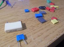
I tested the stability with different capacitive loads as attached and
I could easily drive it to oscilaltion with this two caps in the near...!
With the 1nF 400V and a 10n 630V foil capacitor. I tried with a lot of
different types and with other types of 10n didnt caused oscillation...
What can be the background..?! Simply capacitor ESL, ESR..?!
What kind if capacitnce has a normal speaker cable? This region..?
BTW: I guess thats exactly why an output inductor is a must...
Not because of a heavy capacitive load as this amp handles even 10-22uF
without any problem but there is (can be) a OPS self resonance which
I guess comes into play when the load capacity hits a critical value...
Or is it still some weak point at my OPS..?
RCs should cover all kind capacitive loads in this region?
Attachments
It's kind of a blog or diary now...
Attachments:
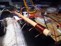
- the right useage of a wooden spoon
- resistor included
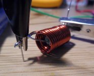
Now it's stable to any kind of capacitive load up to 22uF...
The || R is 1 ohm and it's still working perfectly.
"Calibrated" spoon is cool
Well, that's exactly what the inductor is doing there
One may be surprised, seeing the oscilloscope curves of the square wave (say, 10KHz) on one side of the inductor and on the other side with capacitive load - completely different pictures. 12 turns of wire - and such a big difference!
An output inductor was suggested as necessary for this kind of amplifier by Bonsai in early pages on this thread. It was sage advice that has finally been "discovered" the hard way.
An output inductor was suggested as necessary for this kind of amplifier by Bonsai in early pages on this thread. It was sage advice that has finally been "discovered" the hard way.
Well, on the other hand - a kind of a good practice is to make it as stable as possible with no inductor, and then just add it in order to make it bullet proof
Well, on the other hand - a kind of a good practice is to make it as stable as possible with no inductor, and then just add it in order to make it bullet proof
I agree. There has been an unshakable design objective of reproducing square waves at 100's of kHz, the look of which will be much less than ideal with a series inductor. Hopefully this notion will not need a stake through the heart to ensure it remains dead.
It should be stable even without this L then?
I would be curious that how a similar EF3 behaves at someone else
without output inductor to a 1-10nF load with short wires of course...
BTW: Valery prepare...! I'd like to try a (stable
That's OK - it works
When driving serious capacitance, it heats-up pretty much - square wave at a capacitor means working with your output virtually shorted in the beginning of each half-wave But it does not oscillate.Just a little update:
I built a fast square wave gen with the 7414 IC like here:
Squarewave Testing
and now my results are much cleaner/smoother...
The results:
Input filter: 1k - 82pF
The Ton/Toff asymmetry is coming from the generator.
Is there a way to equalize it somehow..?
I built a fast square wave gen with the 7414 IC like here:
Squarewave Testing
and now my results are much cleaner/smoother...
The results:
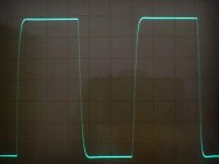
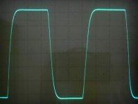
- 100kHz @ 5V/DIV
- 200kHz @ 5V/DIV
Input filter: 1k - 82pF
The Ton/Toff asymmetry is coming from the generator.
Is there a way to equalize it somehow..?
Attachments
Just a little update:
I built a fast square wave gen with the 7414 IC like here:
Squarewave Testing
and now my results are much cleaner/smoother...
The results:
Load = 4R
- 100kHz @ 5V/DIV
- 200kHz @ 5V/DIV
Input filter: 1k - 82pF
The Ton/Toff asymmetry is coming from the generator.
Is there a way to equalize it somehow..?
Some good Op-Amp as an oscillator will make it symmetric. LM358 is convenient for your purpose (you can still use 7414 as an output buffer):
LM2904-N | General Purpose Amplifier | Operational Amplifier (Op Amp) | Description & parametrics
Just a little update:
I built a fast square wave gen with the 7414 IC like here:
Squarewave Testing
and now my results are much cleaner/smoother...
The results:
Load = 4R
- 100kHz @ 5V/DIV
- 200kHz @ 5V/DIV
Input filter: 1k - 82pF
The Ton/Toff asymmetry is coming from the generator.
Is there a way to equalize it somehow..?
Those are your power amplifier results before your inductor?
Did you look at the generator wave form before making this judgment?
Generator: Ok, thanks Valery!
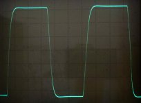
Inductor:
I tried it and the output inductor doesn't make any difference in this test.
I removed it and the result is attached: 200kHz @ 5V/DIV 4R resistive load.
I reduced the input filter to 68pF and even without it the amp is now stable, there's just an overshoot then.
It's not bad, isn't it..? I am so happy that it succeeded finally...
And yes, certainly I checked my both generators and the difference is obvious.
Attachments
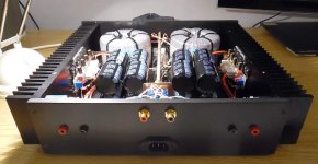
And hopefully the last upadte...
I finally assembled the amp all together and tested and still found one issue related to stability...
Maybe it's useful for others so I share.
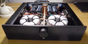
Even though I tested on the bench the output RL (1cm x 12 round + || 1R) wasnt perfectly tuned
and the amp (rather the OPS) started to oscillate to an 820pF ceramic and a 10nF foil cap...
I was very disappointed and tried to remove the || 1R but even so it wasnt enough.
Then I tried with a 8R2 and now it's perfect to any kind/value of caps from pF to uF...
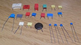
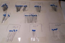
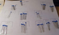
I tried all of my caps as attached they were my testing team now...
I thought the resistor is just for reducing the HF loss but as it seems it should be tuned precisely...
I made the tests with very short wires directly @ the output connectors
with open (I mean with a 10k pot) input and with square wave driven + with all the caps.
Every cap produced a very differrent ringing both in amplitude and freqency.
Even the same valued but different type of caps (ceramic/foil) produced a completely different result.
(BTW: I guess this can be good to method to analyse capacitor behaviour..!)
I hope now I can put any kind of cable/load to the amp without stability issues...
And finally about the SQ: I like it a lot...! It's very clean, airy, strong, etc...
I finally assembled the amp all together and tested and still found one issue related to stability...
Maybe it's useful for others so I share.
Even though I tested on the bench the output RL (1cm x 12 round + || 1R) wasnt perfectly tuned
and the amp (rather the OPS) started to oscillate to an 820pF ceramic and a 10nF foil cap...
I was very disappointed and tried to remove the || 1R but even so it wasnt enough.
Then I tried with a 8R2 and now it's perfect to any kind/value of caps from pF to uF...
I tried all of my caps as attached they were my testing team now...
I thought the resistor is just for reducing the HF loss but as it seems it should be tuned precisely...
I made the tests with very short wires directly @ the output connectors
with open (I mean with a 10k pot) input and with square wave driven + with all the caps.
Every cap produced a very differrent ringing both in amplitude and freqency.
Even the same valued but different type of caps (ceramic/foil) produced a completely different result.
(BTW: I guess this can be good to method to analyse capacitor behaviour..!)
I hope now I can put any kind of cable/load to the amp without stability issues...
And finally about the SQ: I like it a lot...!
It's very clean, airy, strong, etc...Attachments
And hopefully the last upadte...
I finally assembled the amp all together and tested and still found one issue related to stability...
Maybe it's useful for others so I share.
Even though I tested on the bench the output RL (1cm x 12 round + || 1R) wasnt perfectly tuned
and the amp (rather the OPS) started to oscillate to an 820pF ceramic and a 10nF foil cap...
I was very disappointed and tried to remove the || 1R but even so it wasnt enough.
Then I tried with a 8R2 and now it's perfect to any kind/value of caps from pF to uF...
I tried all of my caps as attached they were my testing team now...
I thought the resistor is just for reducing the HF loss but as it seems it should be tuned precisely...
I made the tests with very short wires directly @ the output connectors
with open (I mean with a 10k pot) input and with square wave driven + with all the caps.
Every cap produced a very differrent ringing both in amplitude and freqency.
Even the same valued but different type of caps (ceramic/foil) produced a completely different result.
(BTW: I guess this can be good to method to analyse capacitor behaviour..!)
I hope now I can put any kind of cable/load to the amp without stability issues...
And finally about the SQ: I like it a lot...!
What one has to consider is the reactance of the inductor in Ohms in relation to the damping resistor at the critical frequency, and the overall effect on impedance of these two in parallel.
As frequency increases the impedance of the inductor with also increase thus a resistor in parallel will pass more current. If too small a resistor the net impedance of the buffer would reduce too much.
You can quantify by RC calculations.
- Status
- This old topic is closed. If you want to reopen this topic, contact a moderator using the "Report Post" button.
- Home
- Amplifiers
- Solid State
- Heatsink vs OS stability