Strange... this solution gives great results I tested it with 6R dummy load and with 33uF capacitive load as well... :-o
(I still have some series current limiting resistors going to the OS rails.)
It would be great to really understand this phenomena even if its not a conventional HF compensation...")
Any idea..?
It charges the hidden capacitance created by the OS transistors and the heatsink?!
(I still have some series current limiting resistors going to the OS rails.)
It would be great to really understand this phenomena even if its not a conventional HF compensation...
Any idea..?
And then how this solution works?Cancels capacitance of the predrivers?
It charges the hidden capacitance created by the OS transistors and the heatsink?!
Strange... this solution gives great results I tested it with 6R dummy load and with 33uF capacitive load as well... :-o
(I still have some series current limiting resistors going to the OS rails.)
It would be great to really understand this phenomena even if its not a conventional HF compensation...
Any idea..?
And then how this solution works?
It charges the hidden capacitance created by the OS transistors and the heatsink?!
l'm new to amplifiers but my ef3 I am currently finishing needed very fast devices through the output stages to stop oscillation.
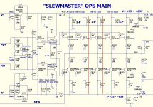
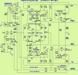
The schematic...
A tried to indicate the 2 separate parts (PCBs) and the pair of wires between narrowed in the middle.
Reduce the gain (add 68R to the LTP emitters)
and also try a 3-7pf cap from VAS out back to the inverting input.
Have you simulated ? I did , and it is only marginally stable with
a "peak" at 2.8mhz !
OS
A tight local FB from the outputs , over the rails , and back to the pre-drivers.
I can create this peak by just not decoupling the pre-drivers.
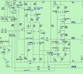
It's a common technique used by OEM's (below - note C110-113 and C107/109).
And as was pointed out C107/109 add Ccb to the first stage of the EF3.
This is almost universal in an OEM EF3.
It's not your input stage , either. My symasui (below 2) runs the EF3 nicely.
You can even be "sloppy" ... mis-wired grounds , no HS ground - not a hint of
oscillation.
OS
I can create this peak by just not decoupling the pre-drivers.
It's a common technique used by OEM's (below - note C110-113 and C107/109).
And as was pointed out C107/109 add Ccb to the first stage of the EF3.
This is almost universal in an OEM EF3.
It's not your input stage , either. My symasui (below 2) runs the EF3 nicely.
You can even be "sloppy" ... mis-wired grounds , no HS ground - not a hint of
oscillation.
OS
Attachments
I tried the Ccb @ predrivers with 22pF and they didnt help but increased the ringing.
Or it works only with the series Rs on the rails?
If there is a parasitic capacitance between the CBs @ the output trs this solution only increases it
and the resistor to HS does the opposite it eliminates this C with chargeing it in phase with the output level.
Am I wrong?
Or it works only with the series Rs on the rails?
If there is a parasitic capacitance between the CBs @ the output trs this solution only increases it
and the resistor to HS does the opposite it eliminates this C with chargeing it in phase with the output level.
Am I wrong?
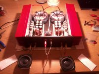
Prototype ready and finally I just finished one channel.
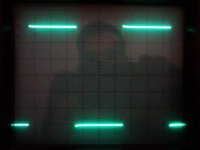
A made a lot of tests with this unconventional stabilisation.
I attach the results of the maybe the most drastic one.
Input: 1kHz 2Vpp
Output: 30Vpp
Load:
1st: 6R
2nd: 100R + 33uF (paralell)
I am condfident...
Now the other channelcomes...
A made a lot of tests with this unconventional stabilisation.
I attach the results of the maybe the most drastic one.
Input: 1kHz 2Vpp
Output: 30Vpp
Load:
1st: 6R
2nd: 100R + 33uF (paralell)
I am condfident...
Now the other channelcomes...
Attachments
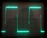
I see the over shoot on the leading edge of the first.
Most likely from no Re on the input pair (too much gain).
My square (simulation) does this on my symasym with <22R
for Re.
For a "prototype" , one should get any possible instability under control.
Edit - looking at the second pix , your unity gain point changes with less load+ C ...
(becomes rounded) , quite the opposite that I have observed ??
OS
Last edited:
I added one more 5.6pF from VAS out to inv-input that helped maintaining the stability,I see the over shoot on the leading edge of the first.
Most likely from no Re on the input pair (too much gain).
My square (simulation) does this on my symasym with <22R
for Re.
but I still have some asymmetric overshooting mainly on the "+" side as attached.
What does asymmetry means?
I removed the OS completely for testing but @ the VAS output the asymmetry is already present.
This can be still beacuse of no Re @ input pair?
And it appears only after a level of driving.
U out max = 50V and it appears up from 20V increasingly with and without loaded VAS as well.
I'll now remove this 5.6pF cap because I am not sure how it looked before this mod...
Attachments

Last edited:
symasym is not truly symmetric , despite it's name.
Just a single ended LTP driving a fancy current mirrored level shifter.
On my "symasui" I fixed this by buffering my active side/mirror side
with matching cascodes - much better .
A true symmetric amp is like (below).
Edit - degenerate those input devices ... that's an order !!
OS
Just a single ended LTP driving a fancy current mirrored level shifter.
On my "symasui" I fixed this by buffering my active side/mirror side
with matching cascodes - much better
.A true symmetric amp is like (below).
Edit - degenerate those input devices ... that's an order !!
OS
Attachments
Okay, okay, I'll try the Re-s in the LTP on the prototype!
I dont want to build a full symmetric, it has too many parts...
And in theory where this asymmetry is most likely created?
Input stage? CCS? C-Mirror? VAS output? HF comp?
(I assume its not from the PS, resistors, layout...)
Do you have some idea how to "debug" it?
For example: temporary replace the CCS and/or the current mirror with a simple resistor...?
It's not a bug , you have a CM on one side of the VAS and an active device on
the other - different impedance's.
I noticed this when I first encountered the sym 5 years ago (simulation).
The negative drive of the VAS is also going through 3 more devices (group delay).
All IPS's that are level shifter based are like this.
(This is why It can't be as fast as a true symmetrical).
Any of these common topologies is just a well defined set of compromises.
PS - HK 680 uses "symasym" as VAS , and I would not have the symasui ....
If I thought this type was not a VERY good amplifier.
Edit - yes ... some variants of this design replace the VAS CM with a diode/resistor.
OS
Ohh, thanks God, after a few hours of struggling it looks like I found it..!!
It was the magic resistor... But keep calm I'll to keep it in place...
After placing the 5p6 from the VAS to the inv-in a forget to adjust its value...
So instead of dropping it out I fine tuned it with a pot to the ideal value (6k8)
and now everything is perfect and totally symmetrical up to 100kHz @ max U level!
I had to interrupt the final tests, cause my R-zobel fired out @ 100kHz... so I'll continue
tomorrow but with this mod I couldnt find any major error now...
So fortunately I dont need to build a "real" symmetrical or use Re @ LTP I hope...
By the way I removed the input C as well, it looks for me completely unnecesary now.
I have nothing HF garbage without it even with long unshielded cables...
Whats the meaning of it..? Slew rate controll..?
In the previous layout I needed it but I'm sure not because of HF noise from outside but for changing the amp's HF behaviour...
Anyway I am happy now so I go to bed finally... Zzzz... ;-)
It was the magic resistor... But keep calm I'll to keep it in place...
After placing the 5p6 from the VAS to the inv-in a forget to adjust its value...
So instead of dropping it out I fine tuned it with a pot to the ideal value (6k8)
and now everything is perfect and totally symmetrical up to 100kHz @ max U level!
I had to interrupt the final tests, cause my R-zobel fired out @ 100kHz...
so I'll continue tomorrow but with this mod I couldnt find any major error now...
So fortunately I dont need to build a "real" symmetrical or use Re @ LTP I hope...
By the way I removed the input C as well, it looks for me completely unnecesary now.
I have nothing HF garbage without it even with long unshielded cables...
Whats the meaning of it..? Slew rate controll..?
In the previous layout I needed it but I'm sure not because of HF noise from outside but for changing the amp's HF behaviour...
Anyway I am happy now so I go to bed finally... Zzzz... ;-)
Last edited:
Input R/C rolls off (attenuates) RF ... PC noise , etc. Considering our
electrically "dirty" world , I have AC RF , input RF , - even my 35A bridge
ground loop breaker has RF considerations.
Back in 1980 , before all this SMPS stuff ...these were only minor considerations.
OS
electrically "dirty" world , I have AC RF , input RF , - even my 35A bridge
ground loop breaker has RF considerations.
Back in 1980 , before all this SMPS stuff ...these were only minor considerations.
OS
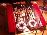
Just to have a clear conscience: I just made it with a floating heatsink at the end...
The solution was: HF filter between the VAS and the OS: series 300R + 22pF (Cbc @ predriver).
Now its insensitive to any heatsink touch, there is no noise and the OS is stable to any kind of load...
The solution was: HF filter between the VAS and the OS: series 300R + 22pF (Cbc @ predriver).
Now its insensitive to any heatsink touch, there is no noise and the OS is stable to any kind of load...
It's NASA baby...
I am not sure if it helps, but strange: touching it with a piece of wire cracks a big one at the speaker...
The foil isnt connected to anywhere... And connecting it to GND even created a hummm...
Hmmm , looks like you have my slewbaby 2 pair with a equivalent symasui
IPS - Yes , you were the one I was trying to advise on that instability
issue.
It seems you did not take the advise. ALL my amps are EF3's now , I can
touch anything short of getting shocked , or do any position - even ground
wrong with no change in anything. Shields and steel near the amps will
only slightly affect some aleady VERY low hum (>-107db).
That's my reference HK680 hum spec , my DIY's are magnitudes lower.
PS - I'M very close quartered in my internal chassis - you can have a quiet amp in a very small chassis !
Amps laying out of the chassis were DEAD silent with ANY grounding
arrangement. I only embellished the cabling as a tiny hum developed
with everything 30mm away from a monster trafo !!
Add the local decoupling , copy the slewbaby/monster. You won't have any
more problems. Would be easy to port to your app.
I studied / copied the Parasound/Pass labs "way" for both my output
stages and general layout - I have matched or exceeded their specs -
(-113 /-115db N +hum).
Change the design and THEN "humbust".
OS
Cortez if that's your schematic you need to
1. Decouple the OPS rails right at the collectors (220uF in // with 0.1 film
2. Isolate your pre driver from driver stage with an RC network in the rail and a c 10 ohm in the collector of each driver. Also your driver damper network values need work. A more conventional network would be 27 ohms and 470 of from the driver base to the V+ Rail.
3. Your input filter fo is too high. It should be at 500 kHz or lower
4. Add a Zobel. Without it you are going to get problems
5 . You need an output L on a design like this OR a very low ULGF otherwise you will get problems
6. As far as I can see you have only a 10 p MIC comp cap - what is your ULGF? For an EF3 1.5 MHz is the upper limit
As OS has remarked, you need to work on above issues and only after that can you address hum problems
Last edited:
- Status
- This old topic is closed. If you want to reopen this topic, contact a moderator using the "Report Post" button.
- Home
- Amplifiers
- Solid State
- Heatsink vs OS stability