Hi all! Just wanted to present some ideas here after many years of thinking on mos fet power amps and reducing switch over distortion with some kind of sliding bias scheme. I have done a lot of reading of many posts here, patents and papers from various sources around sliding bias. My design objectives has been to keep as simple as possible and very easy to adjust quiescent current.
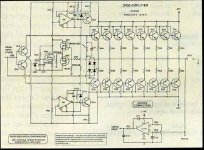
Maybe I'm getting close to something. The circuit presented here is a variation of a standard basic amplifier with mirror LTP followed by a VA, connected to a diamond buffer BJT-Mos Fet output stage. The BJT is basically reversed EF so it's maybe not so amazing. But this opened up for using a few diodes to keep the gate-source voltage of the Mos Fet's high enough to never turn them off.
I have just done some try-outs in LTSpice and fiddling with different values on resistors and diodes, current sources and more. After a while I found this to be working. The output devices 2SK134 and 2SJ49 have really low turn on voltages (0.15--1.45), but by changing R18, R19, I1, I2 other devices should be able to fit.
So, how does it work? When the voltage difference between VA and output is going negative for M2 (positive for M1) the diodes D1 or D2 starts to conduct and keeps this to maximum 0.7 volts. Potentially this could be almost the full swing of the supply rails. The normal thing is therefore to protect this with a zener diode of 12--14 volts. Q9 and Q10 have a drop of 0.6--0.7 volts, so potentially the gate-source voltage should never be less than 0 volts. R16 and R17 takes the voltage difference.
However I was not satisfied because the quiescent current was too high during idle and to low for cut off during full swing. This was fixed by adding D3, changing connection points for R16 and R17 to opposite sides and finding the right value for R18 and R19. With values in the schema the idle current is around 140 mA, cut off current 90 mA during full peak swing of 3.15 A.
The red line is the output voltage and the green line the current through M2. In this burst of 4 cycles a small jump is visible at the end of the green line. This is the jump from cut off current to idle current.
The values of R16 and R17 determine how much current goes through D1 and D2, and the type of diodes also influences the end result much. In order to keep it all simple I ended up using 12 volts Zener types here to get the required current limit for the Mos Fet’s (the maxiumum gate-source voltage is ±14 volts).
Of course there are lot of things to make this into a working amplifier. The current mirrors must be implemented and there are several ways to do that, e.g. with current mirrors to adjust the quiescent current at one point, use power driver transistors instead of the small signal used here, adding a RF filter on the output and more. No smoke in LTSpice
I have no distortion simulation, but the FFT graph shows a nice falling curve with pre dominant even harmonics over the odd ones. If only the reality could be this good!
So please dear community, what are your thoughts on this?
Maybe I'm getting close to something. The circuit presented here is a variation of a standard basic amplifier with mirror LTP followed by a VA, connected to a diamond buffer BJT-Mos Fet output stage. The BJT is basically reversed EF so it's maybe not so amazing. But this opened up for using a few diodes to keep the gate-source voltage of the Mos Fet's high enough to never turn them off.
I have just done some try-outs in LTSpice and fiddling with different values on resistors and diodes, current sources and more. After a while I found this to be working. The output devices 2SK134 and 2SJ49 have really low turn on voltages (0.15--1.45), but by changing R18, R19, I1, I2 other devices should be able to fit.
An externally hosted image should be here but it was not working when we last tested it.
So, how does it work? When the voltage difference between VA and output is going negative for M2 (positive for M1) the diodes D1 or D2 starts to conduct and keeps this to maximum 0.7 volts. Potentially this could be almost the full swing of the supply rails. The normal thing is therefore to protect this with a zener diode of 12--14 volts. Q9 and Q10 have a drop of 0.6--0.7 volts, so potentially the gate-source voltage should never be less than 0 volts. R16 and R17 takes the voltage difference.
However I was not satisfied because the quiescent current was too high during idle and to low for cut off during full swing. This was fixed by adding D3, changing connection points for R16 and R17 to opposite sides and finding the right value for R18 and R19. With values in the schema the idle current is around 140 mA, cut off current 90 mA during full peak swing of 3.15 A.
An externally hosted image should be here but it was not working when we last tested it.
The red line is the output voltage and the green line the current through M2. In this burst of 4 cycles a small jump is visible at the end of the green line. This is the jump from cut off current to idle current.
An externally hosted image should be here but it was not working when we last tested it.
The values of R16 and R17 determine how much current goes through D1 and D2, and the type of diodes also influences the end result much. In order to keep it all simple I ended up using 12 volts Zener types here to get the required current limit for the Mos Fet’s (the maxiumum gate-source voltage is ±14 volts).
Of course there are lot of things to make this into a working amplifier. The current mirrors must be implemented and there are several ways to do that, e.g. with current mirrors to adjust the quiescent current at one point, use power driver transistors instead of the small signal used here, adding a RF filter on the output and more. No smoke in LTSpice
I have no distortion simulation, but the FFT graph shows a nice falling curve with pre dominant even harmonics over the odd ones. If only the reality could be this good!
So please dear community, what are your thoughts on this?
Member
Joined 2009
Paid Member
Looks fun!
In Spice current sources can do some strange things (at least I found that) unless you identify them as 'active load' - right click the current source, go to 'advanced' and inside there is a check-box for 'active load'. This ensures it doesn't force current when there is no reasonable voltage across it.
There is some interesting attempts at some interesting bias with Diamond buffers before, such as the Audio Research D400A.
Attachments
Last edited:
Looks interesting, definite much more interesting than some of the same basic c*** amplifiers somebody keep posting....
Questions are:
1) Does it matter that much with mosfets ? They don't have the same sharp turn on/off as bipolars ?
2) How to make a practical amplifier as the lateral mosfets turn on voltage varies from 0.15V-1.45V....
You might also want to investigate the diode performance of the zeners, maybe replace them with fast switching diodes and make the protection elsewhere....
Hi soekris, thanks
1. Yes it matters because mos fets are voltage-to-current devices and bipolars are current-to-current. Essentially the principals could be the same for bipolars but harder to control. My idea is a poor mans solution. For bipolars I think you really need some kind of current sensing feedback control of the bias (e.g. Madrigal).
2. By matching devices (if paralleled devices) and make bias adjustable.
Yes, the zeners (D1, D2) does matter. I started with 1N914, 1N4148, tried shottky and germanium diodes. The current is very important, therefore the values of R16 and R17 are also important. I think 1N914 had the nicest behaviour just by looking at the graphs, but mos fets needs protection too. 2SK134/2SJ49 already have gate protection zener diodes, but still have a maximum rating for gate-source voltage of +/- 14 volts. The same probably goes for the more modern BUZ900/905 devices.
Last edited:
Hi soekris, thanks
1. Yes it matters because mos fets are voltage-to-current devices and bipolars are current-to-current. Essentially the principals could be the same for bipolars but harder to control. My idea is a poor mans solution. For bipolars I think you really need some kind of current sensing feedback control of the bias (e.g. Madrigal).
2. By matching devices (if paralleled devices) and make bias adjustable.
Yes, the zeners (D1, D2) does matter. I started with 1N914, 1N4148, tried shottky and germanium diodes. The current is very important, therefore the values of R16 and R17 are also important. I think 1N914 had the nicest behaviour just by looking at the graphs, but mos fets needs protection too. 2SK134/2SJ49 already have gate protection zener diodes, but still have a maximum rating for gate-source voltage of +/- 14 volts. The same probably goes for the more modern BUZ900/905 devices.
I mean use fast diode for the bias control, and zeners for protection, don't think it's a good idea to combine, it's not like they're expensive parts....
- Status
- This old topic is closed. If you want to reopen this topic, contact a moderator using the "Report Post" button.
- Home
- Amplifiers
- Solid State
- Sliding bias and diamond mos fet buffer for power amp