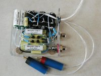
Why don't you ask Mr. Fred Dieckmann? Harry is Fred!transducer said:Over a year ago, Harry Haller posted a shot of his Borbely fet follower:
http://www.diyaudio.com/forums/member.php?s=&action=getinfo&userid=3734
I'll guess Fred has "Taxi driver" loaded in his VCR and stands in front of a mirror: You talking to me? You talking to me? You talking to _me_?Upupa Epops said:Nice devices, but pig's work !


You should see my breadboards - no, better not. 
I don't even use a veroboard, just wire it 3D. Real mess, but ya gotta start somewhere.......
Is Harry REALLY Fred?
Fred is one of the finest engineers on this forum; I should know, I commissioned him to do an I/V and a Sallen Key filter and his work was exemplary. I can't speak highly enough for his mix of theory and practice.
Cheers,
Hugh
[Joke]

End of round 1 !peranders said:
I'll guess Fred has "Taxi driver" loaded in his VCR and stands in front of a mirror: You talking to me? You talking to me? You talking to _me_?
IV schematic
Hello Hugh,
Yes Harry = Fred, since a loooong time ago.
I would love to see a schematic of this IV by Fred. Is it silmilar to Jocko's ?
I also wire 3D just as Jim Williams of Linear Technology experimenting, but my PCB's are neat and tidy.
AKSA said:You should see my breadboards - no, better not.
I don't even use a veroboard, just wire it 3D. Real mess, but ya gotta start somewhere.......
Is Harry REALLY Fred?
Fred is one of the finest engineers on this forum; I should know, I commissioned him to do an I/V and a Sallen Key filter and his work was exemplary. I can't speak highly enough for his mix of theory and practice.
Cheers,
Hugh
Hello Hugh,
Yes Harry = Fred, since a loooong time ago.
I would love to see a schematic of this IV by Fred. Is it silmilar to Jocko's ?
I also wire 3D just as Jim Williams of Linear Technology experimenting, but my PCB's are neat and tidy.
CAN WE PLEASE STAY ON TOPIC!
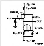
Fred/Harry has been asked about this circuit before by another member, no reply was forthcoming. I was hoping that some of the other members would be able to tell me if the schematic from Borbely is what Fred/Harry used. I was also curious what the extra components in his buffer were for.
I personally don't see any problem with his work. It does the job, doesn't it?
RonS
Some time ago, someone on DiyAudio posted a schematic of a push-pull follower circuit by QSC Audio (I think), which used a current-sensing arrangement to modulate the lower device (in lieu of the 0.22uF cap in the Borbely circuit). I've used similar circuits and can verify that they can work quite well, and will most likely deliver lower distortion than the Borbely circuit posted here.
I can't find the link, but I am sure that it exists somewhere within DiyAudio. Maybe someone knows the link, has the schematic on their computer, or knows how to manipulate the search engine better than I?
regards, jonathan carr
I can't find the link, but I am sure that it exists somewhere within DiyAudio. Maybe someone knows the link, has the schematic on their computer, or knows how to manipulate the search engine better than I?
regards, jonathan carr
This is one of the stupidest posts I have ever read on this forum.Upupa Epops said:Nice devices, but pig's work !
Pedja
Remember The Sock-Puppets.........
"Yes Harry = Fred, since a loooong time ago. "
Also Chance Gardiner, Artnyos', GGrand, and a few other hilariously funny ones See Sin Bin Thread .
"Since moderation takes place here, HarryHaller has behaved well . But the other identities caused a lot of mess and confusion. As we know that all seven identities are the same person, we think that the person known to us as HarryHaller has used these indentities to behave to his own questionable taste whenever he feeled like that, knowing, that his main identity on which he collected expertise and respect and recognition would stay untouched. He knew he could get away with it. "
These times were as funny as hell, and the product of pure genius.
Eric.
Re: Remember The Sock-Puppets.........
why would anyone do that?
mrfeedback said:"Yes Harry = Fred, since a loooong time ago. "
Also Chance Gardiner, Artnyos', GGrand, and a few other hilariously funny ones
Eric.
why would anyone do that?
Well it seems we have a number of people on DIY audio that seem to go to extremes to make another look bad. Or is it just self promontion. What I read is Fred call's em like he sees them, some people can’t deal with that. Like Feedback said some stuff is very funny.
As for prototypes go there nothing wrong with his prototype Upupa Epops. Many years ago Nelson Pass published at article on the A40 amp in audio amateur. Nelson's breadboard was a "ball" of resistors, transistors and caps connecting to the output which were on heat sinks, it was funny but it was still art.

As for prototypes go there nothing wrong with his prototype Upupa Epops. Many years ago Nelson Pass published at article on the A40 amp in audio amateur. Nelson's breadboard was a "ball" of resistors, transistors and caps connecting to the output which were on heat sinks, it was funny but it was still art.
Why, oh why?
Search around for “electronic design”, “breadboarding”, “veroboard”, “prototype”, “Jim Williams” etc.
Pedja
None in this thread is supposed to share my opinion about your post but many of them have already told you why I said that. Check back.Upupa Epops said:Oh really ? Why ?
Search around for “electronic design”, “breadboarding”, “veroboard”, “prototype”, “Jim Williams” etc.
Pedja
Laughing too hard to be mad!
I thought it was cute........ BTW all that stuff is silver soldered and connected with silver wire. It sounds very nice. There's a rumour going around that Erno is a pretty good designer.
The extra caps are because the circuit is AC coupled and powered by single supply voltage.
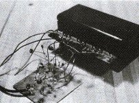
Entry number 2 below in the guess the pig farmer contest ..........
I thought it was cute........ BTW all that stuff is silver soldered and connected with silver wire. It sounds very nice. There's a rumour going around that Erno is a pretty good designer.
The extra caps are because the circuit is AC coupled and powered by single supply voltage.
Entry number 2 below in the guess the pig farmer contest ..........
Attachments
- Status
- This old topic is closed. If you want to reopen this topic, contact a moderator using the "Report Post" button.
- Home
- Amplifiers
- Solid State
- Borbely Fet Follower / HarryHaller?