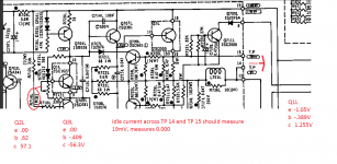
Amp powers up and operates. Realized one heat sink was hot while the other was cold during idle. Check of the idle current on the left side measured 0mV. Adjusting R714 1K pot makes no change.
Though I was able to confirm that the pot is adjusting by monitoring Q1 base and watching Q1 emitter.
Can anyone help in what can be suspect?
Though I was able to confirm that the pot is adjusting by monitoring Q1 base and watching Q1 emitter.
Can anyone help in what can be suspect?
Attachments
Check of the idle current on the left side measured 0mV.
Maybe one of the 0.47 Ohm emitter resistors is open.
Rayma, it looks like 2ea .47 ohm emitter resistors in parallel bringing the resistance to .24 ohms. If one opened the emitter resistor value
then becomes .47 ohm? Can these be checked for open without having to remove from the board?
Sure, there's no need to unsolder them. After the power supply is discharged, just measure the resistance directly across both pairs of emitter resistors.
The meter should read 0.24 Ohms or so. Zero the meter first because of the low resistance.
Good news. Tested the emitter resistors for resistance.
left channel .5 ohms
right channel .5 ohms
the resistance of the clip leads is .26 ohms
so that puts the resistance at .5 - .26 = .24 ohms, half of the paired paralleled .47 ohm resistors.
Decided to give the wire wrapped connections on the left channel amp board a twist using the needle nose pliars.
Now have idle current and was able to adjust to proper setting of 19mV ± 3mV.
Let it sit for 20 minutes and each heatsink was warm.
The schematics I have the test voltages are not legible. If you have a schematic that the test voltages are legible please email to me (rfitts46@comcast.net ). amplifier functions and sounds good but the left channel has no idle current. TP 14 to TP 15 measures 0V. Heatsink is cold to the touch when idling. The base voltage on Q1 is low. Can only get up to 400mV or so when adjusting R714.
The only resistors checked were the emitter resistors. I have not spent a lot of time on this amp. I have never used regularly but am interested in getting the idle current corrected. As stated the last time I played with this the idle current miraculously appeared...in hindsight that in itself is interesting. I thought as a result of twisting the wire ties on the left channel amp board resulted in the idle current reappearing. I have retried retwisting but to no avail. I removed Q1L and Q2L, they are on the same heatsink board so new heat compound could be applied to Q1L. My next step was to disassemble the chassis to a point so the two output boards can be inspected and allow probing from one to the other to determine what differences there are in the predriver area. Currently traveling until Wedn so I have access to nothing. But looking at the posted measurements it appears that the Q1L emitter is low measuring -1.05 should be -1.2. Q1L collector looks good at 1.2V. The schematic has various expected factory measurements but the schematic copies I have these measurements are tough to make out. I am a novice so any direction to focus on are appreciated.
It sounds like you have a bad solder joint somewhere, which was temporarily fixed by moving stuff around.
Going through the main and output boards with some flux and reflowing all the solder joints would not be a bad idea.
Also could be corrosion at the end of a link wire from old flux eating away at the copper.
Going through the main and output boards with some flux and reflowing all the solder joints would not be a bad idea.
Also could be corrosion at the end of a link wire from old flux eating away at the copper.
Peart, thanks for your thoughts...as soon as I get back into town...am planning on disassembling chassis so that both output boards can be gotten to. Will do thorough inspection and start probing both boards for similarities and dissimilarities. Will report back on observations /measurements.
Hey Chris how are you? Yep just can't keep my hands out of something they shouldn't be in. Remember I am the novice...know just about enough to take measurements without blowing something up. Why is the base voltage 150mV lower on the left Bias transistor Q1? How do trim resistors fail...can resistance increase? The collector voltage on the right and left Q1 is 1.2V. So we know that on one side of trimmer the available 1.2V is correct. The low base voltage of -.38V is putting the emitter at -1.03V...which is lower than the -1.2V on the right side Q1 emitter, 200mV lower? Bob
Hi Bob,
You have to measure the voltages in the output stage from the hot terminal. That way you get the real E-B drops. We can't use measurements from ground to these points as they are moving a little bit. So, black lead from your meter into the red speaker terminal, no speakers connected. Red lead to the point you want to measure. Once you take those readings I bet things will make more sense to you (and me!).
Trimmer resistors can crack the outside resistive ring (pushing down too hard can do this). They also oxidize like silverware and lose connection. Turning the control might make contact again, or the connection to the slip ring can get loose. Of course, solder connections can always be difficult to find.
-Chris
Hey Chris....yes you mentioned that when I was working with you on the Crown. Needed to hear it again. I was rereading the notes on the Vbe doubler biasing circuit that you gave me some time ago...thanks. Will remeasure time permitting...later this afternoon. As always thanks.
Hi rfitts46,
Could the bias control be intermittent? That would cause your problem.
These are decent little amps. The later amps (220, 230) sound weird, not in a good way.
-Chris
It's that variable bias loop that seems to be doing it, partially.
To add, the 230 has 22g wiring on the mains transformer's I and O. Another major culprit. (20g on the 220 transformer)
Sort of a built in current limiter. Rather sad.
Of course there's more, but I'm picking on the design too much already.
- Status
- This old topic is closed. If you want to reopen this topic, contact a moderator using the "Report Post" button.
- Home
- Amplifiers
- Solid State
- Nikko Alpha II no idle current left channel