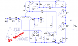
Since the beginning of the Circlophone project, I had always toyed with the idea of making an ultimate test of flexibility and versatility: create a vintage, full-germanium version.
I finally had the time and opportunity to build one.
Some adaptations had to be made, for mainly two reasons: one is obvious, it is the different material bandgap, the other being the slowness of Ge transistors compared to Si: they are litterally orders of magnitude slower.
This required some redesign of the compensations too.
Another problem is the lack of good NPN transistors: this mandated the use of P-darlingtons for the OP, instead of CFP's.
The bias currents also had to be corrected, because of the low allowable dissipation in the VAS and driver transistors.
The result however is still very much a true Circlophone, completely self-adjusting and thermally safe.
It worked almost immediately, with the quiescent current establishing itself at 190mA, just like its silicon brothers.
Now that I have the thing working, I will measure its characteristics and post some oscillograms....
Have fun!
I finally had the time and opportunity to build one.
- It is an interesting test: would a modern topology like the C have been viable in the early sixties?
- An adjustment-free, totally safe amplifier would have been a considerable improvement, but is it actually possible?
Some adaptations had to be made, for mainly two reasons: one is obvious, it is the different material bandgap, the other being the slowness of Ge transistors compared to Si: they are litterally orders of magnitude slower.
This required some redesign of the compensations too.
Another problem is the lack of good NPN transistors: this mandated the use of P-darlingtons for the OP, instead of CFP's.
The bias currents also had to be corrected, because of the low allowable dissipation in the VAS and driver transistors.
The result however is still very much a true Circlophone, completely self-adjusting and thermally safe.
It worked almost immediately, with the quiescent current establishing itself at 190mA, just like its silicon brothers.
Now that I have the thing working, I will measure its characteristics and post some oscillograms....
Have fun!
Attachments
")
Here are some first results:
(Zload=8Ω, Vs=+/-14V)
Iq: 190mA
DC offset: 35mV
THD 1W 1KHz: 0.1%
THD 8W 1KHz: 0.3%
Pmax, onset of clipping: 10W
BW @ 1W, -3dB: 22KHz
Pos and neg SR: 1.4V/µs
First pic is the small signal squarewave response (mind you, it's 1KHz).
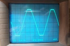
Second pic is large signal SW
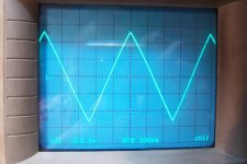
Third pic, linearity
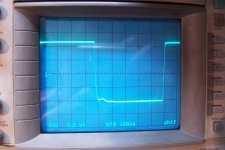
Fourth, clipping behavior
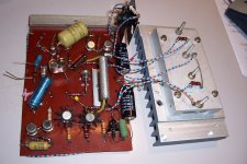
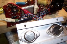
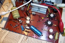
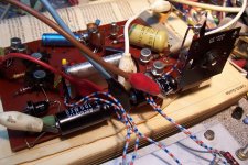
And finally, some more pics of my prototype
Some comments:
It is a mixed bag (what did you expect?): static characteristics are decent, dynamic ones are less glorious, but two things are to be kept in mind: this is a dinosaur from 50yrs+ ago, and it is a first draft: I used the first compensation scheme that appeared to work, and it is rather punitive, to say the least.
There is probably a lot of ground to be gained in this department (but no, it will never be able to compete with even the most modest of Si-based amplifier, there are no miracles), and I am pretty sure it could become a "Hifi" amplifier, according to the standards of the epoch.
So far, I didn't attempt to make a listening test, this will come next
(Zload=8Ω, Vs=+/-14V)
Iq: 190mA
DC offset: 35mV
THD 1W 1KHz: 0.1%
THD 8W 1KHz: 0.3%
Pmax, onset of clipping: 10W
BW @ 1W, -3dB: 22KHz
Pos and neg SR: 1.4V/µs
First pic is the small signal squarewave response (mind you, it's 1KHz).
Second pic is large signal SW
Third pic, linearity
Fourth, clipping behavior
And finally, some more pics of my prototype
Some comments:
It is a mixed bag (what did you expect?): static characteristics are decent, dynamic ones are less glorious, but two things are to be kept in mind: this is a dinosaur from 50yrs+ ago, and it is a first draft: I used the first compensation scheme that appeared to work, and it is rather punitive, to say the least.
There is probably a lot of ground to be gained in this department (but no, it will never be able to compete with even the most modest of Si-based amplifier, there are no miracles), and I am pretty sure it could become a "Hifi" amplifier, according to the standards of the epoch.
So far, I didn't attempt to make a listening test, this will come next
Attachments
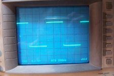
According to the first two square wave looking tests, it is slightly overcomp. Try to get the corners slightly sharper so as to achieve high end imaging. If this costs tone, apply tonal compensation at the power circuit. I'm suggesting to consider the imaging mandatory and then fix the tone later. Other means do exist; however, might as well try it the easy way first.
Dan, that square wave test doesn't show how the amplifier will behave under normal listening conditions. You can see that the amp is overdriven due to the asymmetrical aberrations. It is like testing the response time of a weight scale by hitting it with a hammer.
EDIT: Okay, the first scope shot looks like it's just under the limit, but often that's still too close.
EDIT: Okay, the first scope shot looks like it's just under the limit, but often that's still too close.
Last edited:
Both questions handily answered with two more resistors and two tiny diodes.
Replace r17 with 12k or higher, Replace r16 with 500r trimpot, connect antiparallel diodes to wiper, connect another 500 trimpot as vr between diodes and in+, so then the dial at r16 controls input limit and the added dial at in+ adjusts imaging, if when there's enough capacitance provided across the diodes. 1n4004 type has enough. Better signal diodes could be used if a really tiny value capacitor was added. After testing, the two dials can be replaced with ordinary resistors.
Then, funny little germanium amplifier trumps most high end amplifiers as per imaging/soundstage.
Last edited:
Here are some fresh news: it took some time, because I had a few "problems":
I first made a listening test before attempting any optimization. Following my measurements, I was somewhat expecting deficiencies in the highs department, but I was surprised to find the opposite: if anything, it sounded too bright, with the trebles overly (and unpleasantly) present. OK, this is purely informal, remember: I have tin ears.
I then began the optimization process: at first, all went well, with steady improvements noticeable (objective ones I mean), then after carrying out some mods, I powered the prototype only to see the 18 ohm resistor smoking.
I stopped immediately, obviously, fearing the worst: I tested all the critical transistors, the OP and drivers in particular, and found nothing wrong.
In the end, as I could find nothing wrong, I powered it again and it worked as if nothing had ever happened.
A few episodes later, something similar happened, but with different symptoms: this time the amp was completely dead, unresponsive, not even a smoke signal somewhere.
After some adventures, I found that two of the low power transistors of the circlophone engine were gone, with no apparent reason: probably an errand solder splash or something similar.
After everything was fixed, I was able to finalize my optimization: the improvement for dynamic characteristics is clearly noticeable.
Now, for a 2~3KHz signal, the outlook is similar to the 1KHz waveforms I posted earlier, which is quite a valuable step forward.
Of course, this doesn't change it into into a racehorse, but it becomes almost acceptable by contemporary standards.
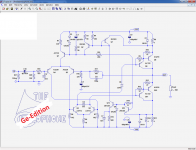
When I find time, I'll post the updated (mostly simplified) schematic.
I first made a listening test before attempting any optimization. Following my measurements, I was somewhat expecting deficiencies in the highs department, but I was surprised to find the opposite: if anything, it sounded too bright, with the trebles overly (and unpleasantly) present. OK, this is purely informal, remember: I have tin ears.
I then began the optimization process: at first, all went well, with steady improvements noticeable (objective ones I mean), then after carrying out some mods, I powered the prototype only to see the 18 ohm resistor smoking.
I stopped immediately, obviously, fearing the worst: I tested all the critical transistors, the OP and drivers in particular, and found nothing wrong.
In the end, as I could find nothing wrong, I powered it again and it worked as if nothing had ever happened.
A few episodes later, something similar happened, but with different symptoms: this time the amp was completely dead, unresponsive, not even a smoke signal somewhere.
After some adventures, I found that two of the low power transistors of the circlophone engine were gone, with no apparent reason: probably an errand solder splash or something similar.
After everything was fixed, I was able to finalize my optimization: the improvement for dynamic characteristics is clearly noticeable.
Now, for a 2~3KHz signal, the outlook is similar to the 1KHz waveforms I posted earlier, which is quite a valuable step forward.
Of course, this doesn't change it into into a racehorse, but it becomes almost acceptable by contemporary standards.
When I find time, I'll post the updated (mostly simplified) schematic.
This would be a good time to cheat, just slightly--a very specific power voltage eliminates both the need and advantage of adding excessive ccs circuits, and "conditional stability" offers the needed imaging, and power circuit tweak compensates for the tonal consequences of conditional stability. Then, of course, you've got a really high end amplifier.
The problem that I see so far, is that stiff compensation all in one spot is like a thick rope too short. Instead, one might be in need of several thinner ropes of just the right length.
The problem that I see so far, is that stiff compensation all in one spot is like a thick rope too short. Instead, one might be in need of several thinner ropes of just the right length.
I tried it, of course, but the circuit is such that only this scheme appears to work: when I try to add the other compensation RC between the VAS bases, the cap value is never small enough. Ideally, I would need a negative capacitor in this place, because the circuit is already inherently overcompensated due to the slowness of the transistors. In practice, the closest approximation is an absent capacitor.
The only transistors in this amp that could be called "fast" are the ASZ20: their advertised Ft is 40MHz. All the rest is much lower (110KHz for the ASZ18)
The only transistors in this amp that could be called "fast" are the ASZ20: their advertised Ft is 40MHz. All the rest is much lower (110KHz for the ASZ18)
by carrier mobility, Germanium is faster than silicon, thus the first transistors suitable for UHF had been pnp germanium "mesa" transistor which had an ft of about 1 gHz. Available is only AF239S today. Germanium does not have a stable oxide, while silicon dioxide is in fact the only real advantage of silicon in terms of fabrication of semiconductor devices. germanium power transistors had been fabricated with alloy technology, which yields huge variances of base width and hence, pn junction width. Together with lower band gap comes a much lower maximum pn junction temp, about 90 degrees max. Thus for equal idle and max power dissipation, bigger heatsinks are necessary.
Hi Elvee, I just got some big Ge power outputs like 2n511a, 2n1011,2sb410, 2sb214 (Big to-3) with some `to-18 cans-2n2567, ac128, 2sa221, 2sa329. I find this Ge version interesting. can i use this Ge that i have and also can i increase the supply voltage around +/-20Vdc.
Another option is, Can I just use the big to-3 as output with silicon drivers? Of all the Circlo version which one is capable on PNP output for just few modificatons.
Thanks..
Another option is, Can I just use the big to-3 as output with silicon drivers? Of all the Circlo version which one is capable on PNP output for just few modificatons.
Thanks..
.Hi Elvee, I just got some big Ge power outputs like 2n511a, 2n1011,2sb410, 2sb214 (Big to-3) with some `to-18 cans-2n2567, ac128, 2sa221, 2sa329. I find this Ge version interesting. can i use this Ge that i have and also can i increase the supply voltage around +/-20Vdc.
They will need to have a Vceo of 40V at least.
Some of the other transistors like the drivers will also require a 40V rating.
For the others, it depends on their position
.Another option is, Can I just use the big to-3 as output with silicon drivers? Of all the Circlo version which one is capable on PNP output for just few modificatons
If only the drivers are Si, you can use the Si value (56 ohm IIRC) for R9 R12.
If you build a full-Si one, except for the output, take a regular C, invert the supplies, the polarity of transistors, diodes and E-cap, and use the Ge value for R10 R13 (10ohm).
Note that this amplifier is for fun mainly: it is HiFi, but according to 1960's standards.....
Thanks..
2SB410 have better frequency properties, but less power. An SI in a Class A preamp stage will work well. SI drivers can be tried.
That's one of my options. Running Class A with Ge outputs might not have enough power dissipation.
.
They will need to have a Vceo of 40V at least.
Some of the other transistors like the drivers will also require a 40V rating.
For the others, it depends on their position
.
If only the drivers are Si, you can use the Si value (56 ohm IIRC) for R9 R12.
If you build a full-Si one, except for the output, take a regular C, invert the supplies, the polarity of transistors, diodes and E-cap, and use the Ge value for R10 R13 (10ohm).
Note that this amplifier is for fun mainly: it is HiFi, but according to 1960's standards.....
Thanks..
Thanks,
I will check on the Vce especially the small preamp Ge trannies if they are capable in 40v range, else i will go to another option as Silicon for all and only the output will be Ge.
- Home
- Amplifiers
- Solid State
- The Circlophone©, Germanium edition.