Well you do explicitly ask for software, and of course it depends
on the purpose you have. However, in many cases I would say
it is rather a matter of hardware. No software has so far come
even come close to the user-friendliness of pen and paper. You
don't have to jot it down on an old envelope like Bob Pease, any
paper will do.
I have been around in the computer business long enough to
be quite desillusioned about the appropriateness of using computers
for many tasks. All too often they just slow you down and create
an obstacle to creativity. They might be good for producing a
nice-looking final schematic for presentation, though.
kaukasion said:the software im using is garbage
and i have a schematic on paper i want to share with yall so i can get answers and general help with it
but i dont have a scanner

Ok, without a scanner it is a problem. Otherwise most of us wouldn't
mind a handdrawn schematic. To the contrary, it is quite refreshing
to see that some people still post those.
While it is more than a drawing program, you could use LTSpice,
the freeware Spice implementation from Linear.
www.linear.com/software
I find that GUI more easy to use and get started with than most
others I have seen.
As a bonus you can simulate your circuits if you wish.
kaukasion said:what version of it should i download?
I think there is only one version. It is called both LTSPice and
SwitcherCAD III. First in the list of software last time I chekced.
Schematics
Jocko and I use the Micro-Cap 7 demo. It draws good schematics and is very easy to use for schematic capture. I really think that's the best freebie program to do schematics with. I use another expensive program for Spice but it's schematics don't look near as good.
I would probably use Microcap 7 for free Spice if I didn't already have a very good program that I am used to.
http://www.spectrum-soft.com/index.shtm
Christer said:
I think there is only one version. It is called both LTSPice and
SwitcherCAD III. First in the list of software last time I chekced.
i cant figure out how to draw a transformer in it?
well here is what i was wanting to do
i like that program very easy for beginners thank you
i was picking apart a very small powersupply just for practice
i drew a schematic of what it looked like was going on
just for practice
i dont know hardly anything
and am a total begginner i just thought that this would be good practice
i havent identified the value of alot of the parts
the R1 is 1/4W 4.7kohm +/- 5%
c1 + c2 seem to be small disc looking capacitors but other than the number 103 on them they tell me nothing yet lol (remember begginner)
c3 is a large cylindrical capacitor black in color top of it has the impression of |<, 10v 6800uf
d1 and d2 seem to just be regular old black diodes
lol anyone wanna help me identify these parts and or point me in the right direction
thanx
Attachments
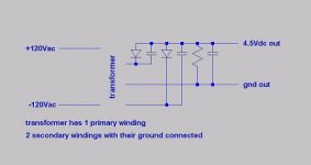
oh yeah and it said on the casing that it was rated @ 500mA output
which is .5A right?
so at 4.5 x .5a
its good for what 2.25W?
lol not much but something to play with
now i need to design and input stage and output stage
with as few parts as possible
this is one hell of a newb project lol
which is .5A right?
so at 4.5 x .5a
its good for what 2.25W?
lol not much but something to play with
now i need to design and input stage and output stage
with as few parts as possible
this is one hell of a newb project lol
Christer said:I have been around in the computer business long enough to
be quite desillusioned about the appropriateness of using computers
for many tasks. All too often they just slow you down and create
an obstacle to creativity. They might be good for producing a
nice-looking final schematic for presentation, though.
Hi Christer,
Are you one of those monks that writes down an assembly program for a micro controller and then convert it to ones and zero’s by hand using pencil and paper?
Kaukasion,
If it is for drawing schematics only, have a look at DesignWorks: http://www.capilano.com/dwmlite.html
It was originally written for the Mac some 20 years ago. It is one of the easiest to learn programs with a nice user-friendly user interface and on a Mac it gives splendid graphic results. It was written by skilled programmers (not engineers) for engineers and with a lot of help of engineers using it. It is available for Windows also.
Cheers
Pjotr said:
Hi Christer,
Are you one of those monks that writes down an assembly program for a micro controller and then convert it to ones and zero’s by hand using pencil and paper?
HI Pjotr,
No, if I program at all nowadays, I prefer high-level languages. I did
it the way you describe with my first computer, though. I didn't even
have an assembler for it, so I had to write assembler code on paper
and then translate manually to machine code and enter that by
hand. It can be useful to do a couple of times as a pedagogical
exercise, perhaps, but it's not a very efficient way to do it on
modern computers. It was a different thing 25 years ago, though,
having only 16KB RAM and only a casette recorder as storage
device.
I have learnt over the years, however, that sometimes or even
often it is better not to use a computer at all to do ceratain
things. I don't know how much time I have wasted over the years
insisting on using computers for things that I realize later would
have been both easier and quicker to do by hand. Too much of
modern software is also rather an obstacle than a help to use
computers efficiently IMHO.
- Status
- This old topic is closed. If you want to reopen this topic, contact a moderator using the "Report Post" button.
- Home
- Amplifiers
- Solid State
- schematic drawing