I´m back home again. Sorry for the delay.
Here comes the uploads.
Mjona, thanks for uploading parts of it. There is more.
Fast Eddie D and Aksa, I have thouroughly grokked what you wrote.
I received the new output devices, mount them tomorrow, incorportate the changes and fire it up again.
Hugh, is there any recommendation as to the quality of this cap?
Electrolytic bypassed with a ceramic or something?
In Bob´s book I read to break the feedback loop and investigate each stage individually. Unfortunately I think this does not work with a singleton stage in real life.
@mjona: power supply integral part of the pcb.
No. What you see on the photos is not the power filter caps, but a parallel bank of output caps. No problem installing a series resistance.
upload scans courtesy of Geoff IIRC. I hope he don´t mind. There are more pages, but they have either nothing to do with the power amp or are already uploaded.
With JLH stuff it is pretty complicated. I wish those reprints were all available in some place. Nobody will have all the papers he ever published and sometimes valuable information will be missing and unobtainable.
-helmut
Here comes the uploads.
Mjona, thanks for uploading parts of it. There is more.
Fast Eddie D and Aksa, I have thouroughly grokked what you wrote.
I received the new output devices, mount them tomorrow, incorportate the changes and fire it up again.
To accommondate these changes, I'd change C5 to 470uF, C7 to 220uF, and
Hugh, is there any recommendation as to the quality of this cap?
Electrolytic bypassed with a ceramic or something?
In Bob´s book I read to break the feedback loop and investigate each stage individually. Unfortunately I think this does not work with a singleton stage in real life.
@mjona: power supply integral part of the pcb.
No. What you see on the photos is not the power filter caps, but a parallel bank of output caps. No problem installing a series resistance.
upload scans courtesy of Geoff IIRC. I hope he don´t mind. There are more pages, but they have either nothing to do with the power amp or are already uploaded.
With JLH stuff it is pretty complicated. I wish those reprints were all available in some place. Nobody will have all the papers he ever published and sometimes valuable information will be missing and unobtainable.
-helmut
Attachments
Last edited:
If you use a capacitor as part of a filter, then quality (parameters) make a big difference to how the filter performs..................Hugh, is there any recommendation as to the quality of this cap?
Electrolytic bypassed with a ceramic or something?...............
BUT !!!!!
we should never use "filters" inside the Power Amplifier. The passband filtering should be done AT THE INPUT.
Then all the RC & CR inside the amplifier do not have to work at their frequency extremes where they begin to act as filters.
When a capacitor is used as a signal coupling capacitor, differences in parameters are almost totally irrelevant. Use an electrolytic where size & cost are a concern, but do ensure it's value is high enough that you DON'T ask it to filter the signal.
Sorry Eddie about my incorrect attribution to ownership of the MOSFET problem to your project.
No need to apologize for being confused. I get confused over who is building what when I browse these threads.
I think it's great that people are building stuff like the JLH amplifier. It is much more of a learning experience than building a chip amp from the datasheet circuit. When I started out in electronics, there were no chip amps; you had to deal with issues like we're discussing right here. It's definitely trickier than op amp and chip amp circuits.
I stated 4r0.
NOT 4ohm.
Can I dwell on that. I do not understand what you are steering at.
I collect you are measuring a voltage drop on a precision resistor. But what are you looking at?
And why 4.0 Ohm?
What would be an indication that the amp is able to deliver the needed current and what not?
Please elaborate, thanks
Fast Eddie D said:It's definitely trickier than op amp and chip amp circuits.
") I find that funny. I initially looked at the chip amps, thinking that you plug in a chip and be done with it, until I found that, if it works reliably at all, it is subject to various degrees of quality due to the layout. Endless discussions on caps here and there, plus numerous additional protective circuits - I thought getting a hand-knitted mosfet amp going was easier.
I find that funny. I initially looked at the chip amps, thinking that you plug in a chip and be done with it, until I found that, if it works reliably at all, it is subject to various degrees of quality due to the layout. Endless discussions on caps here and there, plus numerous additional protective circuits - I thought getting a hand-knitted mosfet amp going was easier.
-helmut
Last edited:
Andrew, what in the world are you talking about?
This fellow is trying to make his amp stable.
After it is stable, then it is time to be concerned about the quality of a given cap.
One of your problems, helmut, may be that you are using that very large group of caps for the output blocking cap. A single cap is a much better idea. Short paths are essential for stability. Also not crossing paths of a high current line with something like a base or gate on a device.
I'd simplify your set up, and keep the wires short, use a single cap of any quality, with short leads to between the board and the cap.
Ground wires *count* and running multiple grounds can cause problems including instability.
Chip amps - the discussions are about optimizing designs, not just making a good amplifier work. Fwiw the easiest path is a single LM3886.
_-_-
Helmut,
In regard to the foregoing comments I notice the red input capacitor is close to the multiple electrolytic ones at the output - I see that as waving a red flag in front of a bull. Bear's advice is nice in regard to the use of one output capacitor - it is advisable that you remove the ones that are closest to the input capacitor and reserve the spot for the one furthest away for the one you want to use - whatever the value. If you cannot resolve the other issues he raises, the question arises should you adopt the board layout devised by Linsley-Hood - with short flying leads etc.
Since MOSFET devices can be finicky and given the difficulties you are facing it would not seem a bad idea to build the circuit using the Linsley-Hood board with Darlington Output Transistors and get that going first - and then do the MOSFET modifications.
Last edited:
This stage is so different to any common emitter or common collector or whatever that I have difficulties to understand.
-helmut
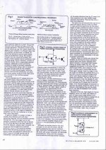
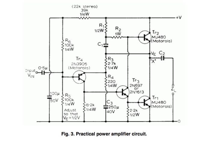
In case this was still confusing, the operation can be understood quite simply once you understand the third main way single transistors can be used: common base. In common-base configuration the input is at the emitter and the output is at the collector. It is a non-inverting amplifying stage.
So in your circuit, the input signal passes through 2 common-emitter stages. Each is inverting, so the result it a non-inverting amplification. The feedback then sees a common-base stage followed by a common-emitter stage, for a net inverting amplification (negative feedback!).
The topology of the feedback is often called "series-shunt", which is the same used in the more modern differential amplifier (LTP) followed by a common-emitter.
jason
Ca
Why would you think that this project was going to be any different? There's more opportunity to fudge the layout with a discrete circuit.
Endless discussions on caps here and there, plus numerous additional protective circuits
Unless a capacitor is causing your problem, you should not focus on this. If you can get it to work with ordinary parts, then you think about this.
thought getting a hand-knitted mosfet amp going was easier.
Nope.
it would not seem a bad idea to build the circuit using the Linsley-Hood board with Darlington Output Transistors and get that going first - and
Good idea. Sort this out first.
Helmut,
In recent years electrolytics have improved enormously, driven by switch mode power supplies. Many are now rated to 100KHz and beyond, so if you seek a good electro, by all means use your audiophile versions like Black Gates and Cerafines, but I found the smps rated electros at 85C working temperature or higher (up to 105C) are very good sonically.
Hugh
Which of my comments/posts are you referring to?Andrew, what in the world are you talking about?.................
22, 33, 40 or 42?
Are you building an 8ohms capable amplifier, or for some other impedance?Can I dwell on that. I do not understand what you are steering at.
I collect you are measuring a voltage drop on a precision resistor. But what are you looking at?
And why 4.0 Ohm?
What would be an indication that the amp is able to deliver the needed current and what not?
Please elaborate, thanks
-helmut
This is an nominally 8 Ohm rated amplifier.
What parameters do you measure with the procedure you outlined to test its current capablility?
-helmut
What parameters do you measure with the procedure you outlined to test its current capablility?
That´s why I used the Panasonic FC´s. Unfortunately those specialities are not readily available. They only had smallish values and I had to parallel....use your audiophile versions like Black Gates and Cerafines
-helmut
Last edited:
Ok, we have a starting point.
An 8ohms rated amplifier will see a maximum demand of Vpk /8Rload, when a sinewave drives a resistor.
Speakers are complex loads and music is not a simple single sinewave.
The results in speaker current demands that are much more than the same resistor would draw.
A single wideband speaker will draw a peak current that can be as high as 1.5times the peak current into your 8r0 resistor.
A 2way speaker with a crossover typically demands at least twice the current that a 8r0 resistor demands.
Many speakers are worse than that. Some with real music signal will demand more than 3times the 8r0 resistor current and tests have shown demands exceeding 5times the resistor current.
There's our second point. The amplifier must be able to supply lot's of current into speakers.
If they start to limit the current the effect is similar to voltage clipping, except this time it is current clipping.
Your amplifier will both voltage clip and current clip if overloaded beyond it's capability.
The 3rd part.
How much current do you want to supply to avoid current clipping?
50% more than the resistor, or 100% more than the resistor, or 200% more than the resistor, or much more?
You can measure the maximum unclipped output voltage and see how this varies for different resistive loads.
That is where I was suggesting you use a 4r0 resistor for your testing. It lets you see how much the amplifier is struggling, or not, to deliver current in excess of what an 8r0 resistor would draw.
I suggest you don't want to see the output voltage collapsing, at your chosen current demand test.
I aim for <<1dBV @ 1/2 rated load resistance. Most of my amps can mange with just -0.4dBV to -0.6dBV into a 4r0 load.
And I expect them to similarly do well into 2r7.
Last edited:
Helmut, dear fellow.
Best not jump to far in any direction.
Best to sequentially figure out the problem.
Best to state what you have done when asked, for example, whose layout are you using. (apparently your own??)
I would not do a new layout or decide to change the input, or discard the caps in advance of figuring out to a higher degree of certainty what is going on now.
You want to limit the variables, and not change multiple variables at the same time.
If you do make ur own layout, you'd need to be aware of some basic ideas that relate to how to create a reasonable layout, ie. routing.
You might want to first layout the circuit using "manhattan" type prototyping or using a general purpose copper perf prototype board.
Finally, best to stick to one login?
_-_-bear
PS. pretty sure I have seen JLH circuit boards for sale online, maybe ebay.
@AndrewT: I can follow you now. Thanks.
So happened in post#31. I know this thread is already pretty long.
I have done many many layouts, but none of them were any reasonable power, let alone HF.
I always avoid prototyping board, rather make a decent pcb - usually less trouble. At some point you are going to need a pcb and then everything is different anyway in the land of parasitic capacities.
thanks,
-helmut
Best to state what you have done when asked, for example, whose layout are you using. (apparently your own??)
aquataur said:>Is the layout on your board JLH, or yours or someother??
Mine.
So happened in post#31
. I know this thread is already pretty long.Some very good advise.I would not do a new layout or decide to change the input, or discard the caps in advance of figuring out to a higher degree of certainty what is going on now.
You want to limit the variables, and not change multiple variables at the same time.
If you do make ur own layout, you'd need to be aware of some basic ideas that relate to how to create a reasonable layout, ie. routing.
I have done many many layouts, but none of them were any reasonable power, let alone HF.
You might want to first layout the circuit using "manhattan" type prototyping or using a general purpose copper perf prototype board.
I always avoid prototyping board, rather make a decent pcb - usually less trouble. At some point you are going to need a pcb and then everything is different anyway in the land of parasitic capacities.
Don´t understand you here.Finally, best to stick to one login?
thanks,
-helmut
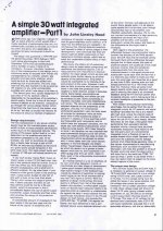
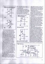
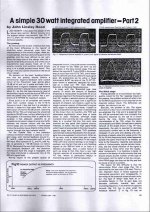
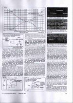
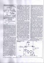
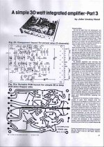
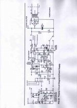
You probably saw kits of the still popular 10-15W class A, JLH '69 design that the OP title confusingly refers to. However, I'm quite sure you saw the thumbnail of a 1980 Darlington 30 watter and the following schematic attachment that refers to his actual 30W Mosfet amplifier design back in #15. It dates from ca. 1982 but neither is anything like the basic 4-transistor JLH '69 attached below, apart from a singleton input stage.PS. pretty sure I have seen JLH circuit boards for sale online, maybe ebay.
Ian,
in retrospect I agree, referring to the 69 design was somewhat unhappy, however I thought this design is well known (unlike the 80´s simple 30W design) and it shares the singleton input state with it - which is what I wanted to know about initially.
This thread has subsequently taken a different (better) direction, which is not reflected in the thread title too well.
This is all about the 79/80ies 30W darlington, resp. 50W mosfet simple amp.
Bear,
I have made up my mind. I agree making changes over changes is leading nowhere, but one of the things that has to change is a few fundamental layout problems I realize are wrong:
#1 input and output needs separation.
#2 decoupling caps need relocation
#3 output caps need relocation.
#4 better ground layout
Before I start cursing with protoboards, I make a new layout.
-helmut
Whilst you are around, Helmut, if you haven't seen this already, you might like to look at some of Paul Kemble's notes and revisions of JLH mosfet designs in addition to those original JLH comments posted from the HiFi News and record review article. A Paul Kemble web page - JLH mosfet amplifiers.
Good Luck
Good Luck
- Status
- This old topic is closed. If you want to reopen this topic, contact a moderator using the "Report Post" button.
- Home
- Amplifiers
- Solid State
- JLH 1969 first amplification stage, need explanation