Hello,
I started to refresh my Marantz unit, and it seems that I'm going to change almost everything inside. Only ceramic and film caps will remain. I already replaced the electrolytic caps and all resistors with metal film.
I pulled out the old transistors and measured them. While they are not leaking at all, hfe is a bit wild between them so I'd like to replace them.
I added the schematics for the boards in question. I'd like an opinion if I can replace them with low-noise BC327/BC337 as I have good access to those, for cheap. I can get lots and match hfe on pairs. Also BC550/BC560. Both pairs have different gain codes so I can match almost all transistors from the amp.
I'll list the transistors I found:
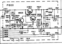
Power Supply: H802 - 2sc945p (hfe 237) in the datasheet P is 200-400
H803 - 2sc945q (hfe 189)in the datasheet Q is 135-270
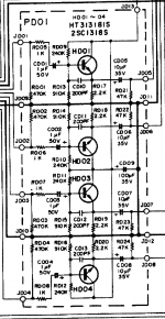
Buffer Board: HD01-HD04 - 2sc1328T (measured hfe was between 481 - 595)
- datasheet specs hfe at 360-700.
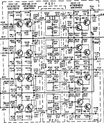
Tone Board: HE01 - HE04 - 2sc1327S (measured hfe was between 338 - 486)
- datasheet specs hfe at 260-520.
HE09 - HE12 - 2sc1222 I guess. Transistors have C1222 written.
- measured hfe was 417 to 735. Datasheet lists it wrong as EBC, it's actually ECB. And has a weird code (2E51A) that doesn't match the datasheet for HFE rating.
HE05-HE08 and HE13-HE16 - 2sa733q (measured hfe 160 - 192)
- Q is a rating of 135-270.
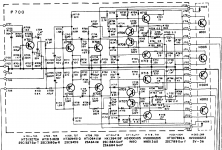
Power Amp:
I haven't gotten to tear down the pcb but the transistor numbers are consistent with the schematic.
2sc1327 S or T hfe of 260-700.
2sc1318 Q or R hfe of 85-240.
2sc945 Q hfe 135-270
2sa641 M schematic has different letters for hfe rating. I have no idea.
2sa684 G or F schematic has different letters for hfe rating. I have no idea. this is a larger to92 package.
I'd like to replace all since working on this unit is a real pain. I don't want to go back inside for the next 10 years, I just want to enjoy it. Right now everything is teared down from the amp so while I'm reacaping, re-resistoring I'd re-transistor as well")
The output transistors are 2SD315, and they seem in working order. The package is TO66 so if they fail I need to adapt TIP41. But those I can access more easy, no need to replace them now.
So, besides the larger to92. can I replace everything with low-noise BC327/BC337 or BC550/BC560 type transistors with matching HFE values?
I started to refresh my Marantz unit, and it seems that I'm going to change almost everything inside. Only ceramic and film caps will remain. I already replaced the electrolytic caps and all resistors with metal film.
I pulled out the old transistors and measured them. While they are not leaking at all, hfe is a bit wild between them so I'd like to replace them.
I added the schematics for the boards in question. I'd like an opinion if I can replace them with low-noise BC327/BC337 as I have good access to those, for cheap. I can get lots and match hfe on pairs. Also BC550/BC560. Both pairs have different gain codes so I can match almost all transistors from the amp.
I'll list the transistors I found:
Power Supply: H802 - 2sc945p (hfe 237) in the datasheet P is 200-400
H803 - 2sc945q (hfe 189)in the datasheet Q is 135-270
Buffer Board: HD01-HD04 - 2sc1328T (measured hfe was between 481 - 595)
- datasheet specs hfe at 360-700.
Tone Board: HE01 - HE04 - 2sc1327S (measured hfe was between 338 - 486)
- datasheet specs hfe at 260-520.
HE09 - HE12 - 2sc1222 I guess. Transistors have C1222 written.
- measured hfe was 417 to 735. Datasheet lists it wrong as EBC, it's actually ECB. And has a weird code (2E51A) that doesn't match the datasheet for HFE rating.
HE05-HE08 and HE13-HE16 - 2sa733q (measured hfe 160 - 192)
- Q is a rating of 135-270.
Power Amp:
I haven't gotten to tear down the pcb but the transistor numbers are consistent with the schematic.
2sc1327 S or T hfe of 260-700.
2sc1318 Q or R hfe of 85-240.
2sc945 Q hfe 135-270
2sa641 M schematic has different letters for hfe rating. I have no idea.
2sa684 G or F schematic has different letters for hfe rating. I have no idea. this is a larger to92 package.
I'd like to replace all since working on this unit is a real pain. I don't want to go back inside for the next 10 years, I just want to enjoy it. Right now everything is teared down from the amp so while I'm reacaping, re-resistoring I'd re-transistor as well
The output transistors are 2SD315, and they seem in working order. The package is TO66 so if they fail I need to adapt TIP41. But those I can access more easy, no need to replace them now.
So, besides the larger to92. can I replace everything with low-noise BC327/BC337 or BC550/BC560 type transistors with matching HFE values?
Attachments
2sa733 = KSA992
2sc945, 2sc1222 = KSC1845
I wouldn't use BC transistors in a japanese amp.
Why is that? Aren't they compatible? I don't have access to ksa/ksc.
I could match the gain with new transistors
Many Jap amps are quite critical of the transistors used, particularly in the output stages. Its not just gain, they actually differ slightly in absolute turn on volts (maybe different manufacturing techniques and doping back then) which can be a big factor where critical bias voltages are needed and generated. For example replacing the drivers and outputs may give a low or no quiescent current that is non adjustable (without altering other components in the bias network). There can also be very real stability issues due to differing inter junction capacitance.
That said, the small signal stages, while showing no benefit for swapping devices, should show no real problems either.
That said, the small signal stages, while showing no benefit for swapping devices, should show no real problems either.
The hfe variation is a non issue thanks to the action of negative feedback. Whether you uses an hfe of a 100 or 800, the circuit would still perform essentially the same. If an hfe of 400 is the lowest of what is in there already, then I would say that was actually pretty high even by todays standards.
Honestly, you won't gain anything by replacing these.
Honestly, you won't gain anything by replacing these.
2sa733 = KSA992
2sc945, 2sc1222 = KSC1845
I wouldn't use BC transistors in a japanese amp.
I seem to be able to get locally 2sc1845 and 2sa992. Should be the same?
The hfe variation is a non issue thanks to the action of negative feedback. Whether you uses an hfe of a 100 or 800, the circuit would still perform essentially the same. If an hfe of 400 is the lowest of what is in there already, then I would say that was actually pretty high even by todays standards.
Honestly, you won't gain anything by replacing these.
Only for those transistors.
In the tone board I have 2sa733q with 160 lowest. But that is in spec with the datasheet as well.
I thought about replacing them as I thought they are old and might give up at some point, and then I see everyone is recommending to match transistors gain.
hfe variations will have a minimal effect at any part of the circuit. Your biggest problem is the other characteristics (not hfe) of the transistors in the power amp causing serious problems if you start swapping them for other modern types. You would need to rework and change some component values.
The preamp stages will work with pretty much anything.
There is no real reason to suspect the transistors will fail... as a general rule that doesn't happen. They should be as good as the day they were made.
The preamp stages will work with pretty much anything.
There is no real reason to suspect the transistors will fail... as a general rule that doesn't happen. They should be as good as the day they were made.
Ok then.
I will still take out the small transistors from the power amp boards, and test them for gain/leakage and see if there's anything wrong with them that could be seen that way.
I will try and get 2sc1845 and 2sa992 as they are ECB and BC series are EBC.
This way I will have some original spares for the final stage if anything happens along the way.
I'd leave 'em be. They wont show any problems... you are more likely to cause problems by heating them and testing them. Reverse biasing transistor junctions (to the point where they conduct) can in certain cases permanently degrade the noise figure of the device. That's more applicable to devices with very thin junctions layers such as RF transistors but is something to be aware of.
Reverse-bais won't happen in any stage unless it is severly overloaded. Just clipping an amp playing it too loud won't do it. Giving an input stage 10V RMS from a speaker output or sound card might, and if a failed power amp stage sticks to the rail it might. But certainly not if the amp is working.
The only failure mechanisms that would be of any consequence are die contamination and heat (or both at the same time, from desodering/soldering certain non-hermetic package types, which is why Mooly said leave them alone unless they're broken). Your unobtainium TO-66 outputs are hermetic, so unless they are overheated they'll never go bad. I've seen some small signal types get noisy from die contamination. They don't outright fail - they give a warning signal that sounds like an off-tuned FM radio with the bass turned WAY up. Sort of a rumbling hiss. Usually not loud, but enough to be annoying. Encapsulated TO-92's won't do it (usually), but the older types with a little plastic shell over the die flag, "sealed" with epoxy goop at the base definitley can. Especially when being soldered/desoldered. If moisture gets in it can corrode, and if heated it will boil....
The only failure mechanisms that would be of any consequence are die contamination and heat (or both at the same time, from desodering/soldering certain non-hermetic package types, which is why Mooly said leave them alone unless they're broken). Your unobtainium TO-66 outputs are hermetic, so unless they are overheated they'll never go bad. I've seen some small signal types get noisy from die contamination. They don't outright fail - they give a warning signal that sounds like an off-tuned FM radio with the bass turned WAY up. Sort of a rumbling hiss. Usually not loud, but enough to be annoying. Encapsulated TO-92's won't do it (usually), but the older types with a little plastic shell over the die flag, "sealed" with epoxy goop at the base definitley can. Especially when being soldered/desoldered. If moisture gets in it can corrode, and if heated it will boil....
Ok, so then I shouldn't replace anything, even if I can get 2sc1845/2sa992?
My original issue with this amp is that at random one channel or the other would just drop out. Then it would randomly fade in again. This unit does not have a relay protection circuit.
The only way I could make the channel come back after dropping out was to increase the volume past 12 o'clock. If I dialed it back down immediately it would drop again. I had to keep it for a few seconds past 12 o'clock then dial it back down and it would stick. But for 5 minutes or so. And both channels dropped out at random. So I was suspecting a transistor for this behaviour. That's why I'd like to replace the ones that are not critical as I could eliminate some suspects. Also, the buffer/tone board are a pain to work on as they are on the bottom and have to take out lots of wires so I can access the backside of the board for soldering jobs.
Power amp boards are more easy to access, take out. I would like to limit the issues only to those boards
I'm suspecting a pot. Also could be a switch or a jack. Somewhere at line level. This reeks of a mechanical problem, not electronic. Due to the high negative feedback in the line stages, even if a transistor were to drop its gain by 50% you'd never notice it in the sound. You might measure in increase in distortion, but we're talking .01% going to .05%. If a transistor goes out entirely, it won't bias at all. If it gets noisy, you'll get that thunder rumbling (which may be intermittent). But large changes in the signal level indicate an oxidized contact somewhere.
'One channel or the other dropping out'
Could be a number of reasons for that. Always start with the basics which means measuring voltages.
When the fault appears measure the DC voltage on the positive end of that 3300uf speaker coupling cap. The voltage should be approximately one half of the full supply voltage. Compare faulty to good states. Does it alter drastically ?
I notice the power amps use those weird diodes SV-3A. They are known troublemaker generally but its a bit of coincidence if both were failing randomly. The DC voltage check mentioned above would show if the problem were in the power amp stage though.
Also check the supplies to the various stages when it fails. Its a common PSU but always always check supplies as a first step in faultfinding.
I cleaned all pots and buttons with deoxit before, there was no more scratchiness at volume knob but the issue was still there. I whacked every switch with spray.
As I said before, I have rebuild the amp completely. The only original parts that are still there is the large transistor 2SD315 from the Power Supply, and all the ceramic/film capacitors. The rest is new for power supply, buffer, tone amp board. The only thing I haven't yet touched are the power amp boards.
The unit is a Marantz 4230 receiver. It has that rare Quadradial setup, the early surround
I can use it in 4 x 15W or 2X30W. I will use it in stereo.
There are two power amp boards, each with two channels.
I have replaced all parts for the boards that I'm interested in and that I'll use, that are in the signal path.
There are also some other boards, like matrix decoder bla bla that I only replaced power supply electrolytic capacitors on. So they don't short the power supply.
So given the complexity of the steps to be taken until I can replace a part on this unit, I prefer to do it now for everything that's worth replacing without affecting the operation of the unit.
If I manage to find equivalent transistors for the lower stages, I will replace them.
I won't touch the small signal transistors from the output boards, but I will replace all of the resistors/electrolytic caps. Film and ceramic stay.
There are some 1N60 germanium diodes on the output boards. I have some BAT41 in case they leak bad.
Right now I'm in the middle of the restoration.
I cleaned all pots and buttons with deoxit before, there was no more scratchiness at volume knob but the issue was still there.
Perhaps the volume pot is beyond hope, if the wiper just doesn't make reliable contact below 12:00.
You need to isolate the pot itself. Try putting it at full setting, and using the incoming signal to lower the volume. If you no longer get dropouts at low volume then it's the pot. If you do, then something downsteam is responding to the signal level.
I've had really weird things do this. I've had pre-in/pre-out jumpers get intermittent. And signal-level dependent because of the properties of the oxide. This can happen especially since you leave them in place and never move them. And occasionally an oxidized speaker connection will develop a high 'resistance' that you can sort of temporarily 're-set' by blasting it for a few seconds. Then it goes back to acting silly when the volume is reduced. Think outside the box as to where an intermittant might be. Pehaps even a headphone jack that's supposed to cut out the speakers when a plug is inserted. I hate 1/4" plugs in general because they're flaky.
If that 3-diode bias string that Mooly is worried about goes bad it will take out the output stage. It won't just act funny. Putting in three 1N4148's in its place is a common preemptive fix. The other is to put *four* 1N4148's in parallel with it. It will do nothing until the bias stack fails. When it does it will clamp the bias at about 2 amps. Which will run hot as hell, but at lest you'll know to look into it ASAP when it does.
Last edited:


- Status
- This old topic is closed. If you want to reopen this topic, contact a moderator using the "Report Post" button.
- Home
- Amplifiers
- Solid State
- to92 transistor replacement