Hi folks, recently I bought a nice Sony TA-5650 with the famous V-fets,
besides changing the diodes that is already done, I wanna do a complete upgrade in both preamp and amplifier sections.
Ok, it's a 40 years old topology, but it sure has it's potential...
Let's exume this old body, talk about it's faults and how to make it competitive with the top amplifiers in the modern days.
First, the amplifier section.
besides changing the diodes that is already done, I wanna do a complete upgrade in both preamp and amplifier sections.
Ok, it's a 40 years old topology, but it sure has it's potential...
Let's exume this old body, talk about it's faults and how to make it competitive with the top amplifiers in the modern days.
An externally hosted image should be here but it was not working when we last tested it.
An externally hosted image should be here but it was not working when we last tested it.
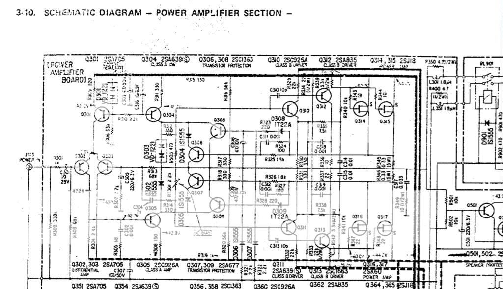
First, the amplifier section.
In other words, let the forum do the work you would like done for you 
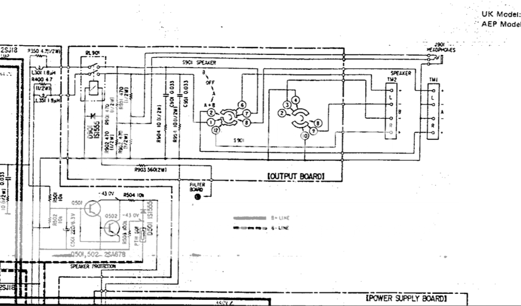
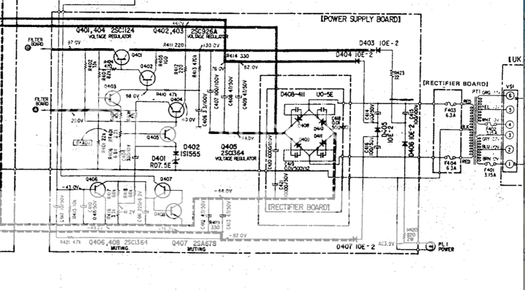
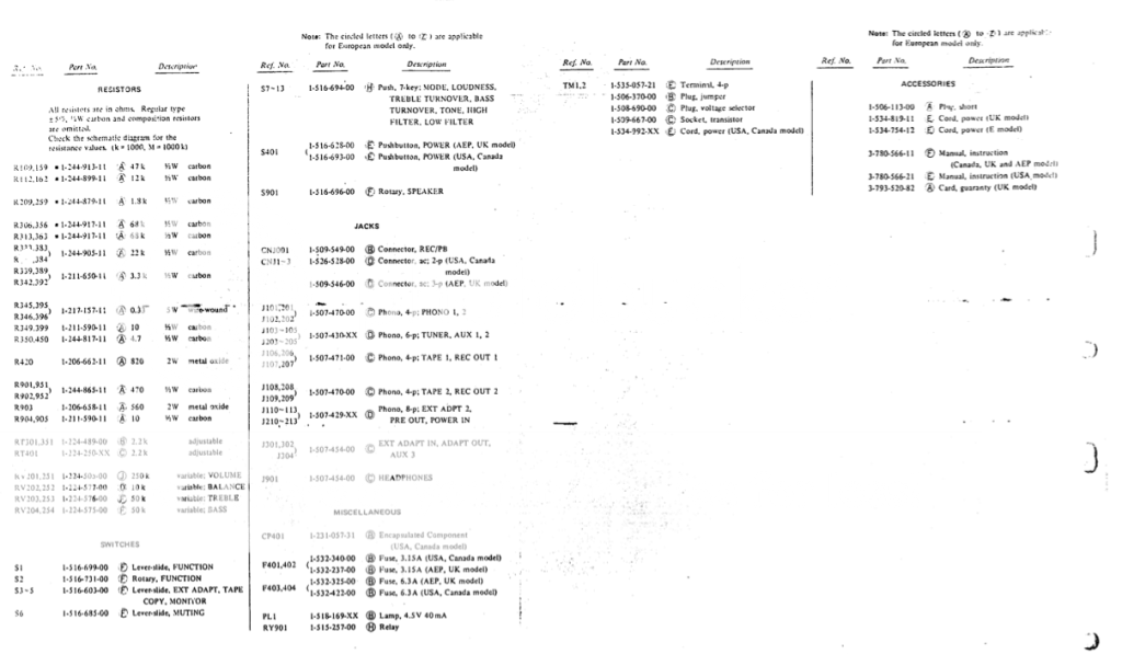
D05 in the power supply needs to be replaced by two diodes in series with the center tap grounded. See if you can figure out why.
Some resistors need changing in the overcurrent protection circuit of the power amplifier. Google it - there has been mention of this here on the forum as well, a search should help.
Some semiconductors in the driver section for the VFETs could be changed, as the availability of high voltage pre-driver transistors was not that good. You will find that the PNP and NPN parts here are not really complements. When exchanged with more modern parts, a slight adjustment to compensation caps is needed.
The pre-driver circuit is not trivial and caters for compensation of mains voltage change, which is important for VFETs since the current through them depends on Vgs as well as Vds.
A resistor in the input differential to VAS connection can be optimized for better input pair balance.
THe double diode in the bias string must be thermally connected to one of the pre-drivers which is close to it on the board. The rubber tube that does this often disintegrates and the amp will be thermally unstable.
There is a number of things that can be done to the preamp section - paradoxally replacing the small VFET in the RIAA circuit with a small MOSFET will improve it's performance (a number of resistors and capacitors can also be optimized for even better performance, also the unobtanium low noise Sony transistor can be changed with a 2SC2240 is done, for a bit less noise).
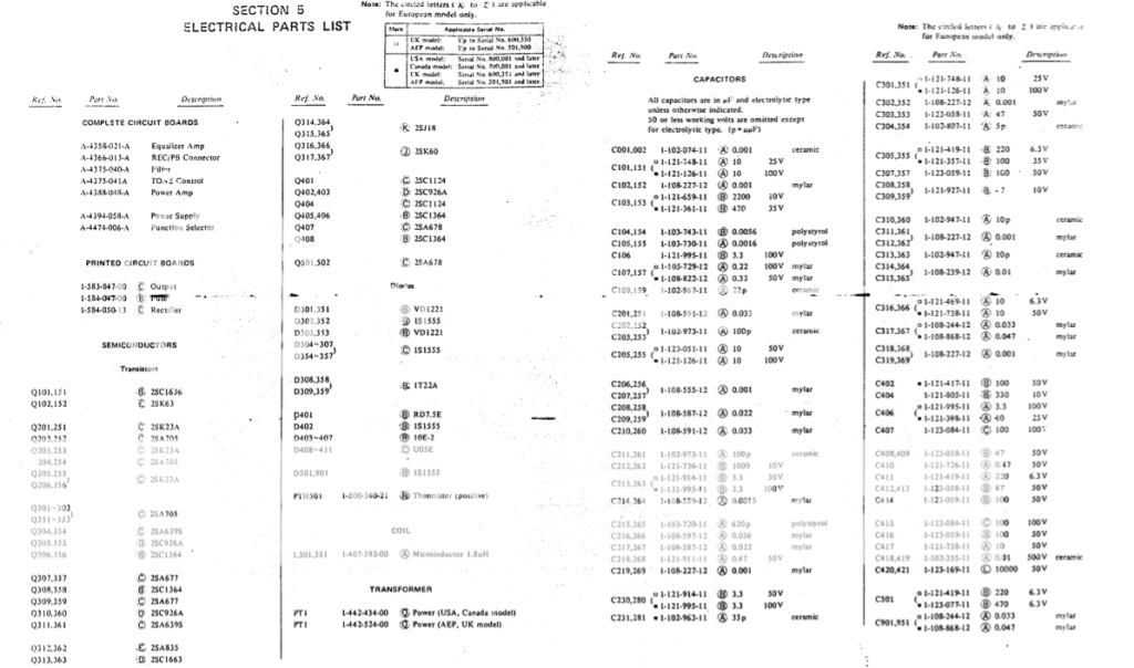
In any case replace the small electrolytics on the supply rails (C303/307 etc.) by quality modern 63-100 V low-ESR types (Panasonic FC or similar Nichicon, Elna, Rubycon etc. - cheap caps are never worth the trouble). These are paramount to stability, and you sure don't want them V-FETs going up in smoke.
Basically you can replace all of the small electrolytics. C301 should be a 10µ bipolar or low-leakage type. C305 actually cleverly protects the input transistors in case of a fault that has the output go up to positive supply - these are only rated at 50 V, thus could be damaged if the output stays above +6V for a longer time. (High-voltage low-noise transistors were not available at the time.) I would expect an 6.3 V cap that old to be seriously leaky though. Maybe you can obtain a lowish-voltage polar low-leakage type somewhere? Otherwise one would have to look for replacement types of equal performance but higher breakdown voltage (not that easy, as these are high beta, fairly high fT types... KSA992 maybe?).
Measure voltage drop across R304 and R309 and compute currents. I(R309) should be pretty much exactly 2x I(R304). I would not necessarily expect good DC balance in an amp of this vintage.
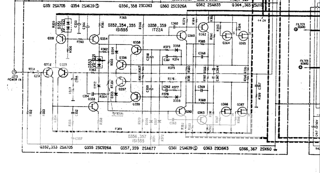
(Add 50 for right-channel part names.)
Basically you can replace all of the small electrolytics. C301 should be a 10µ bipolar or low-leakage type. C305 actually cleverly protects the input transistors in case of a fault that has the output go up to positive supply - these are only rated at 50 V, thus could be damaged if the output stays above +6V for a longer time. (High-voltage low-noise transistors were not available at the time.) I would expect an 6.3 V cap that old to be seriously leaky though. Maybe you can obtain a lowish-voltage polar low-leakage type somewhere? Otherwise one would have to look for replacement types of equal performance but higher breakdown voltage (not that easy, as these are high beta, fairly high fT types... KSA992 maybe?).
Measure voltage drop across R304 and R309 and compute currents. I(R309) should be pretty much exactly 2x I(R304). I would not necessarily expect good DC balance in an amp of this vintage.
(Add 50 for right-channel part names.)
- Status
- This old topic is closed. If you want to reopen this topic, contact a moderator using the "Report Post" button.