Without actually examining one its hard to say but something like that could make a difference.
Once you understand the mechanisms for hum and noise then it becomes easier to understand.
Even as little a fraction of an ohm (0.01 and below) can cause massive problems. So the thicker traces of one of your boardscould be an attempt to overcome this issue.
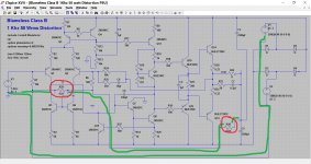
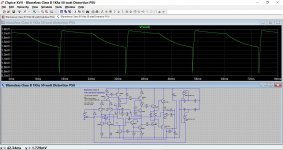
I don't know if this will help or not but its a simulation of a well known design. I have deliberately added two 0.01 ohm resistances in the ground trace to deliberately allow the power supply to generate a small volt drop across this resistance. The two graphs show the resistors initially shorted (so a true zero ohm ground) and then in place.
The two deliberately added resistances are in red. The ground path is green.
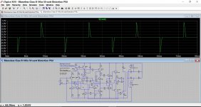
This shows how the hum level increases by the addition of this tiny resistance. Notice the scales at the left of the graph. And that is just caused by adding 0.01 ohm.
Once you understand the mechanisms for hum and noise then it becomes easier to understand.
Even as little a fraction of an ohm (0.01 and below) can cause massive problems. So the thicker traces of one of your boardscould be an attempt to overcome this issue.
I don't know if this will help or not but its a simulation of a well known design. I have deliberately added two 0.01 ohm resistances in the ground trace to deliberately allow the power supply to generate a small volt drop across this resistance. The two graphs show the resistors initially shorted (so a true zero ohm ground) and then in place.
The two deliberately added resistances are in red. The ground path is green.
This shows how the hum level increases by the addition of this tiny resistance. Notice the scales at the left of the graph. And that is just caused by adding 0.01 ohm.
Attachments
I doubt corrosion would do it. Copper naturally tarnishes in minutes if the conditions are right, but once it has done that it won't go worse or go higher resistance.
Plugs and sockets are always suspect but if its consistently OK with one board and not the other then I doubt it would be anything like that.
Plugs and sockets are always suspect but if its consistently OK with one board and not the other then I doubt it would be anything like that.
Hi Dan K,
Can you take a few photos (3 left, centre and right) of the component and track side of the board and send it to me. I'd like to compare it with my 25.25 boards and see if I can pick up if there's a track or component error. I'll drop you a PM with my e-mail address.
Kevin
Can you take a few photos (3 left, centre and right) of the component and track side of the board and send it to me. I'd like to compare it with my 25.25 boards and see if I can pick up if there's a track or component error. I'll drop you a PM with my e-mail address.
Kevin
Last edited:
I still can't find the cause of this. Could it be that the 60Hz 110v transformer is the cause? I've swapped the transformer across from the good amp and the buzz stays with the copper boards.
You mean this amp is a 110 volt 60Hz model and you are using it on 230 vac 50Hz via a matching transformer.
If so then that could be a problem area. A 60Hz only transformer will have less iron in the core than one rated for 50Hz meaning that the transformer could saturate. Its possible that could be an issue.
That's what I'm thinking Mooly. I'll need to try it on a 240V traffo.
Sorry Kevin, I'm working away from home at the. Moment and I don't have either the amp or my PC to upload the pics to dropbox. I'm quite sure that there are no PCB errors, as I have a 2nd 25/25 to compare with.
Sorry Kevin, I'm working away from home at the. Moment and I don't have either the amp or my PC to upload the pics to dropbox. I'm quite sure that there are no PCB errors, as I have a 2nd 25/25 to compare with.
Gentlemen, Massive thanks for your help, however I've still not managed to fix the 100Hz buzz from my Bedini 25/25.
...but I might be close.
last night I discovered that the 680R resistor in the feedback loop of both amp modules are reading high at 737 and 740R. I've ordered a pair of replacements, but until they arrive it's fingers crossed.
I also noticed that the 18k resistors were both reading high at 18.65 and 18.3 - my thinking is that these are not so critical as the 680R.
I also replaced all the power transistors with MJ802's - it sounded very good before. Will be interesting to hear if there is a difference. Perhaps ferret (Kevin) would be good enough to share some details on the possible improvement. certainly didn't remove or change the hum at all.
That sounds a bit suspect. Does the colour code indicate 680 ohms or are they in fact 750 ohm resistors that were fitted ?
Check also that the replacements read 680 ohm (to confirm your meter is OK).
Measuring in circuit can be misleading due to interaction with other components and also any residual voltage (even a few millivolts) affecting readings.
Check also that the replacements read 680 ohm (to confirm your meter is OK).
Measuring in circuit can be misleading due to interaction with other components and also any residual voltage (even a few millivolts) affecting readings.
Hi Dan K and Mooly. I came back to this thread for research reasons. Dan K did you manage to get the Bedini sorted out as far as the 100 Hz hum is concerned? While reading through this, I recalled that the Bedini PSU board has two separate voltage feeds to each channel. There is a 1 Ohm 3 Watt resistor in the 0 Volt rail per channel, which in turn are connected to the earth point/reservoir cap 0 V point. If the resistor on the faulty channel is cooked, this would likely cause an issue.
Regards, Kevin
Regards, Kevin
Hi Ferret, yes I did sort the 100hz buzz! The 100ohm front end decoupling resistors on the negative rail on both boards simply had a link wire in place of the resistors! I replaced with a resistor and the hum was gone.
I do now wonder if a further step up in dynamics and performance could be achieved by directly linking the front end to the back and using an SLB PSU. Something to ponder.
Also, even with the lightly decoupled front end (using 100Ohm resistors) the 100hz buz is still there if you put your ear right up to the speakers. You can get rid of it alltogether by going CRC with a 0.47Ohm power resistor and 4 off PSU caps.
Hi Dan. Seems like me you are busy with other things and browse through the threads as you get a chance.")
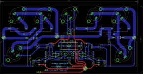
AAMOI, I chap I met here on the forum (South African stays in Johannesburg) did a new layout of the 25.25 PCB for me. My originals are shot - tracks lifting off etc. They are slightly larger than the original and double sided. I had ten made (JLC) but still need to get them finished off - drill holes on the angle aluminium so that I can get the power transistors mounted and a suitable cabinet. The heatsinks I have will be considerably larger than the originals - 6 x more radiating area.
I gave a pair to an audio friend (valve amp aficionado) and he has built them up and on the go. He said he matched the BC550/560s in the front end and has a 2.5mV on one channel and 3.2 mV on the other. He has incredibly sensitive speakers and has not reported any hum or buzz on either channel. He also used a single 500 VA toroidal, and 4 off 10 000uF caps and a 35 Ampere bridge rectifier.
Attached is the schematic and layout picture of the PCB etc.
Regards, Kevin
Attachments
That's pretty darned close to zero.
No, Alan just went for a vanilla PSU. Nothing fancy. I intend to use a CapMX for mine though. I also want to try out some ZTX450/550s instead of BCs. They have almost identical specs to the original MPS8099/8599. I am also struggling to get hold of decent quality 2N5416/3044s so may use BD139/140s -10s though, or the Toshiba TTA/TTC004s. But tested on a bench with a variac.
No, Alan just went for a vanilla PSU. Nothing fancy. I intend to use a CapMX for mine though. I also want to try out some ZTX450/550s instead of BCs. They have almost identical specs to the original MPS8099/8599. I am also struggling to get hold of decent quality 2N5416/3044s so may use BD139/140s -10s though, or the Toshiba TTA/TTC004s. But tested on a bench with a variac.
- Status
- This old topic is closed. If you want to reopen this topic, contact a moderator using the "Report Post" button.
- Home
- Amplifiers
- Solid State
- Bedini 100/100 (802mod) high DC offset problem