I looked up their latest amps on their website. The "Duo 125" for example has an idle power dissipation of just under 60W ( they quote it in BTU/hr which is understandable if you are a heating installer but daft otherwise). From what I can glean your KSA-100 is now idling a little higher than that. So at least you can have peace of mind that your amp is no less class A than the latest models.
Technically, it is not the class A itself that makes Krells sound good. That's just how the original Krells were implemented with the technology and know-how at the time. Also a good marketing device. If the Krell factory tells you it is better now and it sounds better then who are you or we to argue with them?
But I take your point if what you actually wanted was a restored KSA-100 with original parts for the sake of authenticity. It sounds like the Krell folk thought you wanted it brought up to a higher sonic standard and be less wasteful of energy to boot.
In the end, I would agree with them that indeed I DO want an amp that sounds better and runs cooler than the original. It just would have been nice if that would have been explained to me in detail when I was at the factory. Explain how and why the amp will now run cooler, way cooler than an original KSA 100, so that I understand what is happening.
Customer service lacking?
That post from 2 years ago shows it spendidly.
http://www.diyaudio.com/forums/solid-state/267557-refurbished-krell-ksa-100-a-4.html#post4194157
the left shows the ClassA distortion where there is zero crossover distortion. All that is seen is the inherent distortion of the basic amplifier.
Note the level of 2nd harmonic @ ~-90dB
The right diagram shows the ClassAB distortion (low bias, low heat). Again the 2nd harmonic @ ~-90dB
If you were to subtract all of the left from the right, you would end up with a display of the added distortion created by the ClassAB when using crossover to switch between the upper devices and the lower devices.
Because the 2nd harmonic levels were subatabtially the same then the difference is near zero. i.e. crossover distortion added virtually no 2nd harmonic. Crossover distortion is substantially higher order distortions starting at the 3rd harmonic and extending almost to infinity.
The modified ClassAB Krell KSA100 has presumably used their more advanced knowledge to reduce the crossover distortion to less than what is shown in that old post. i.e. the crossover is less audible.
The ClassAB gives less heat.
You win all round !
I am sure they could have told you all of that. I am sure they could have let you hear three different versions to help you to decide which version you wanted for whatever price they were asking you to pay. i.e. compare old ClassA to Old ClassAB to New ClassAB and maybe even a fourth new ClassA (real ClassA not the sliding bias version). But they didn't and that I class as poor customer service given the prices they charge.
Last edited:
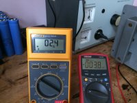
Just finished calibrating my newly acquired Krell KSA-100 Mk 2.
Bias: 560 mV over the 1 Ohm emmiters.
Drawing from the 220 Volt AC line: 3 amps.
DC Offset 135 mV left channel 85 mV right channel.
With DC Offset trimmers (hardly reachable and hard to find) I could get +/-1.5 mV when fully warmed up.
Unit is completely original and very clean inside.
Datecode on Spragues is week 52 year:1986
Any idea why the DC Offset has increased over the 30 years of servicelife?
Maybe components that age and the heat that makes them drift?
http://www.diyaudio.com/forums/attachment.php?attachmentid=595542&stc=1&d=1485771281
Attachments
did you check input offset?
Did you set the output offset with the input shorted?
Did the output offset change when you connected a source?
The output offset may have been adjusted to suit a source that had an output offset of the opposite polarity. That's the downside of using DC coupling. The output offset can wander all over the range.
You really need some form of monitoring of offset and an alarm, or automated protection.
No source connecteddid you check input offset?
No, wil do that.Did you set the output offset with the input shorted?
No source connected yet will connect pre-amp today which I will check before for any offset.Did the output offset change when you connected a source?
Okay, understood.The output offset may have been adjusted to suit a source that had an output offset of the opposite polarity. That's the downside of using DC coupling. The output offset can wander all over the range.
How? I'm not a technician, with a highquality cap somewhere or outputtransformerYou really need some form of monitoring of offset and an alarm, or automated protection.
")
AC coupling automatically blocks input offset AND sets the DC gain to ~0dB.
That combination results in an output offset that varies little and does not vary with the Source, nor vol pot setting. A nice "no thinking" set up that is nearly speaker safe.
DC coupling does not block input offset and sets the DC gain to roughly the same as the AC gain.
This results in an output offset that can vary with temperature and/or with vol pot setting and/or with source selected and/or with Source On/Off.
I have recommended that DC coupled power amplifiers have at least:
A DC servo to control the output offset.
A mute on the input that detects and isolates a source that has an offset at it's output.
A warning that the DC servo is nearing it's limit of offset range cancellation.
A speaker isolation that reacts to excessive output offset.
These will protect your speakers from most of the risks associated with DC coupling.
AC coupling automatically blocks input offset AND sets the DC gain to ~0dB.
I'm not sure how you get 0dB as a DC gain. Wouldn't the DC gain tend to approach - (minus) infinity if you were quoting in decibels.
For example, 1uV output from an amplifier for 100 volts input would be a gain of -160db.
1 pico volt output for the same condition would be -280dB.
Ever smaller quantities tending toward minus infinity.
So how does AC coupling set the gain to 0dB (which is how it reads) ?
AC coupling set the gain of the overall amplifier chain to something approaching minus infinity. For a 1000 volts DC applied to the input you would expect to see 0.00000 volts at the output. Same 'gain' as an open circuit.
It was just how it read, that was all.
AC coupling set the gain of the overall amplifier chain to something approaching minus infinity. For a 1000 volts DC applied to the input you would expect to see 0.00000 volts at the output. Same 'gain' as an open circuit.
It was just how it read, that was all.
First I got rid of the 20 & 9 mV's with the inputs shorted.
Then I connected the pre-amp and got rid of any residual DC Offset.
Unit is deadsilent now.
No mechanical hum or over the loudspeakers.
I decreased the bias over the 1 Ohm emitters to 350 mV's
On the 52V rail that's 73 Watts quiescent current.
How do I calculate the Class A specs over 8/4 and 2 Ohms?
Thanks for your support Andrew so far well appreciated.
My kind is the worst, cognition about this matter but no real experience or knowledge, sorry.
the KSA100 is a ClassAB Push Pull amplifier that never leaves ClassA when the output current is less than the amplifiers ClassA output capability. It's the same for ALL ClassAB amplifiers.
eg. set the output bias of a single pair to 100mA.
The maximum ClassA output current is ~2*100mA = ~200mA and that is a peak value (not AC. nor rms).
You have an output current of 200mApk, therefore the maximum ClassA Power is I²R/2 = 0.2²*8/2 = 0.16W into 8r0
Now increase the output bias to 2A. The maximum ClassA output is ~4Apk.
Therefore maximum ClassA power is 4²*8/2 = 64W into 8r0.
The Krell KSA100 ia usually set to 2.6A bias shared between the 4pairs of output devices.
The maximum ClassA is ~5.2Apk.
The maximum ClassA Power is 2.6Apk²8*ohms/2 = 108W into 8r0. The excess above 100W is due to the fact that you can't quite retain control by both upper and lower devices when one group are down to nearly zero current. The other group are starting to operate in ClassB and taking over the job of supplying current and retaining control via the NFB.
Working back from 100W into 8r0 yopu need both upper and lower groups controlling output currents of 5Apk and that is 2.6Abias ±2.4A of control range.
It looks like the bottom 200mA is where the low current half is starting to switch off and lose control.
This would show up in a simulation if the near saturated modelling was accurate, but this is the range where the modelling is not accurate, so I don't know how much a simulation would confirm when the low current cevices are starting to turn off.
If you reduce your bias a little you can assume that the peak ClassA output current is just a listtel below that doubled bias value. it gets you close enough to the answer.
The Push Pull nature of operation hides the transistion from ClassA to ClassAB and you don't hear that transistion when the high currents are demanded by the speaker at extreme SPL.
For all of the above the standard formula applies:
P= IV= I²R = V²/R when working in DC, or sinewave AC
When using sinewave peak values the formula becomes:
P= Ipk*Vpk/2 = Ipk²R/2 = Vpk²/R/2
Last edited:
0dB tells us that the gain is 1 (one)So how does AC coupling set the gain to 0dB (which is how it reads) ?
AC coupling set the gain of the overall amplifier chain to something approaching minus infinity. For a 1000 volts DC applied to the input you would expect to see 0.00000 volts at the output. Same 'gain' as an open circuit.
It was just how it read, that was all.
Input a 1Vdc signal and with a gain of 1 you get an output of 1Vdc.
When the DC blocking capacitors are added the DC gain becomes 1 (0dB)
If you remove the DC blocking capacitor the input accepts and passes DC signals.
The NFB also passes those DC signals and the DC gain is Rupper/Rlower + 1 and equals the AC gain which is set by the same equation.
I originally posted
Note I said "sets the DC gain to ~0dB.", when the amplifier is AC coupled.AC coupling automatically blocks input offset AND sets the DC gain to ~0dB.
If one removes the AC coupling capacitors then the DC gain and the AC (within the amplifiers passband) will both be the same.
Last edited:
the KSA100 is a ClassAB Push Pull amplifier that never leaves ClassA when the output current is less than the amplifiers ClassA output capability. It's the same for ALL ClassAB amplifiers.
eg. set the output bias of a single pair to 100mA.
The maximum ClassA output current is ~2*100mA = ~200mA and that is a peak value (not AC. nor rms).
You have an output current of 200mApk, therefore the maximum ClassA Power is I²R/2 = 0.2²*8/2 = 0.16W into 8r0
Now increase the output bias to 2A. The maximum ClassA output is ~4Apk.
Therefore maximum ClassA power is 4²*8/2 = 64W into 8r0.
The Krell KSA100 ia usually set to 2.6A bias shared between the 4pairs of output devices.
The maximum ClassA is ~5.2Apk.
The maximum ClassA Power is 2.6Apk²8*ohms/2 = 108W into 8r0. The excess above 100W is due to the fact that you can't quite retain control by both upper and lower devices when one group are down to nearly zero current. The other group are starting to operate in ClassB and taking over the job of supplying current and retaining control via the NFB.
Working back from 100W into 8r0 yopu need both upper and lower groups controlling output currents of 5Apk and that is 2.6Abias ±2.4A of control range.
It looks like the bottom 200mA is where the low current half is starting to switch off and lose control.
This would show up in a simulation if the near saturated modelling was accurate, but this is the range where the modelling is not accurate, so I don't know how much a simulation would confirm when the low current cevices are starting to turn off.
If you reduce your bias a little you can assume that the peak ClassA output current is just a listtel below that doubled bias value. it gets you close enough to the answer.
The Push Pull nature of operation hides the transistion from ClassA to ClassAB and you don't hear that transistion when the high currents are demanded by the speaker at extreme SPL.
For all of the above the standard formula applies:
P= IV= I²R = V²/R when working in DC, or sinewave AC
When using sinewave peak values the formula becomes:
P= Ipk*Vpk/2 = Ipk²R/2 = Vpk²/R/2
Thanks for your elaborate answer.
So when I lower the bias over the 1 Ohm emitters around .350 Volts the Class A calculated will be:
8 x 0.350A = 2.8 Amps
P = 2.8² x 8 = 63 Watts peak Class A @ 8 Ohms
and 31.5 Watts RMS?
Instead of 4 amps it now takes 2.5 amps when idling from a AC line of around 225 Volts.
Last edited:
that sounds wrong.
Each pair passes the same current from +ve rail to -ve rail. The bias curent is simply the bias current.
If you have 4pairs of output devices, then the single bias is repeated three more times, giving a total bias = 4 times the single pair bias.
4 * 0.35A = 1.4A total bias.
Maximum ClassA is almost double this: 2*1.4A = ~2.8Apk
Maximum ClassA power = ~2.8Apk² * 8r / 2 = ~31W
the maximum ClassAB Power is Vpk² / Rload / 2
This is likely to be around 160W into 8r0 for a KSA100
But that is not what you need nor want when looking at maximum output power.
I gave the formula earlier
Does your KSA100 have 8pairs of output devices per channel?8 x 0.350A = 2.8 Amps
Each pair passes the same current from +ve rail to -ve rail. The bias curent is simply the bias current.
If you have 4pairs of output devices, then the single bias is repeated three more times, giving a total bias = 4 times the single pair bias.
4 * 0.35A = 1.4A total bias.
Maximum ClassA is almost double this: 2*1.4A = ~2.8Apk
Maximum ClassA power = ~2.8Apk² * 8r / 2 = ~31W
the maximum ClassAB Power is Vpk² / Rload / 2
This is likely to be around 160W into 8r0 for a KSA100
instantaneous peak power is a consideration when a component has a fixed absolute maximum rating that must never be exceeded.P = 2.8² x 8 = 63 Watts peak Class A @ 8 Ohms
But that is not what you need nor want when looking at maximum output power.
I gave the formula earlier
When using sinewave peak values the formula becomes:
P= Ipk*Vpk/2 = Ipk²R/2 = Vpk²/R/2
Last edited:
Andrew, post #92
My argument was far more simple than that, simply that if you AC couple an amplifier then you reduce the DC gain from input to output to (numerically) zero. It can not be otherwise. If you apply any DC voltage to the amplifier input you will see zero voltage at the amplifier output. Expressed in db that is theoretically -infinity.
With a blanket statement of saying that AC coupling reduces the gain to.... 'and some figure', then it is assumed you are treating the amplifier as a whole, from input to output. That is how most readers would interpret that.
That the internal structured gain of a normal AC coupled amplifier is still (numerically) 1 when AC coupled misses the point. That gain is not accessible to the user.
To not elaborate on the meaning, or assuming knowledge makes it difficult for less knowledgeable readers to understand.
I now see what you are getting at.
Look back at my original statement and you will see why I could not follow your argument.
I said:
The AC coupling automatically blocks the input offset
The AC coupling sets the DC gain to ~0dB
Both statements are correct.
The gain is: [Rupper / Rlower] + 1
Rupper = resistance alone
Rlower = resistance plus DC blocking capacitor.
For AC signals in the passband the capacitor has near zero impedance and the AC gain is determined by the resistances alone.
For DC signal the capacitor has near infinite impedance and thus the DC gain becomes [Rupper/infinity] +1 = [0]+1 = 1 (+0db)
If the capacitance is not quite infinity, then the [0]+1 could be [~0.000001]+1 giving a DC gain of ~0dB
Look back at my original statement and you will see why I could not follow your argument.
I said:
note there are two statements in there. Separated by an "AND"AC coupling automatically blocks input offset AND sets the DC gain to ~0dB.
The AC coupling automatically blocks the input offset
The AC coupling sets the DC gain to ~0dB
Both statements are correct.
The gain is: [Rupper / Rlower] + 1
Rupper = resistance alone
Rlower = resistance plus DC blocking capacitor.
For AC signals in the passband the capacitor has near zero impedance and the AC gain is determined by the resistances alone.
For DC signal the capacitor has near infinite impedance and thus the DC gain becomes [Rupper/infinity] +1 = [0]+1 = 1 (+0db)
If the capacitance is not quite infinity, then the [0]+1 could be [~0.000001]+1 giving a DC gain of ~0dB
Last edited:
Your exactly right there!that sounds wrong.
Does your KSA100 have 8pairs of output devices per channel?
Each pair passes the same current from +ve rail to -ve rail. The bias curent is simply the bias current.
If you have 4pairs of output devices, then the single bias is repeated three more times, giving a total bias = 4 times the single pair bias.
4 * 0.35A = 1.4A total bias.
Maximum ClassA is almost double this: 2*1.4A = ~2.8Apk
Maximum ClassA power = ~2.8Apk² * 8r / 2 = ~31W
the maximum ClassAB Power is Vpk² / Rload / 2
This is likely to be around 160W into 8r0 for a KSA100
That's what the German audiomagazine 'Stereoplay' in March 1986 measured at 8 Ohms with a Krell KSA-100 Mk 2 and 280 Watts at 4 Ohms and 400 Watts at 2 Ohms. Another typical thing they measured was it's soft clipping behaviour starting at 145 Watts and it's almost flat dampingfactor from 172 at 50Hz and still 168 at 10 kHz.
Yes I have 4 pairs of Krell A and AA TO3's (probably selected MJE15003/4 NPN/PNP complementary pairs) outputtransistors per channel.
It drives the Watkins woofers in my old Infinity's QLS wonderfull.
Strange thing though is that this is the first amplifier that doesn't start mechanical humming (transformers) when driving the Watkins and not only the lows are better but also the complete frequencyspectrum has gotten much better.
Thanks again.
- Status
- This old topic is closed. If you want to reopen this topic, contact a moderator using the "Report Post" button.
- Home
- Amplifiers
- Solid State
- Refurbished Krell KSA 100