I have built this from a kit on ebay.
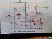
Its a jlh and uses the schematic.
I had been using it on test speakers without a problem and until I added a speaker protection kit.
I thought its was a sensitive kit until I decided to measure the speaker outputs.
It shows 7vdc across them.
Anyone know what I need to do to fix this or what it maybe?
On that schematic it says adjust so that VE = half . Does this mean half supply voltage? My supply is 22.4 vdc and at VE to gnd is 9.99vdc
There is also r10 and c6 which have been added to design is this needed ?
thanks
Attachments
C2 is either bad or wired incorrectly. To double check, put a moderate value resistor (say, 330 or 470R) across the output and recheck the voltage. If it drops to zero, leave the resistor in place. If it's still 7V (or something else significantly non-zero), check the cap and wiring.
I am not sure why this amplifier would need a speaker protection kit since it is AC coupled and employs a great big electrolytic coupling cap on the output?
Did you measure the voltage on the output with no load connected? There is no path for the minute amount of leakage current through the electrolytic output capacitor with no speaker connected. (You can add a 1K resistor from the output to ground to deal with the current.)
Did you measure the voltage on the output with no load connected? There is no path for the minute amount of leakage current through the electrolytic output capacitor with no speaker connected. (You can add a 1K resistor from the output to ground to deal with the current.)
The other thing I would mention is that it is somewhat unlikely that 2N3055 if indeed that is what you are using would have sufficient beta for use in this circuit.
Slightly increase the value of R5 to get the outputs centered at half supply. (Just add a small resistor in series, maybe 10K)
Slightly increase the value of R5 to get the outputs centered at half supply. (Just add a small resistor in series, maybe 10K)
That's the ever-popular John Linsley-Hood class A amp of 1969 - JLH'69 for short. There are lo-o-o-ong threads for it here already.
It works fine with many thousands built but perhaps the speaker protector circuit is not connected appropriately.
'Agreed though, a DC protection relay is a waste of time and money on an AC coupled output anyway.
It could be useful for the dual-rail 1996 version but not here. Solve both problems and lose it.
The voltage was with no load.
I measured it with the protection disconnected
I have just measured under load and on the 200 m volt setting dc on meter it shows on start up a tiny signal that decreases to 0 after 7 seconds
I added speaker protection because of the on off thump ,I have been listening to it on test speakers for for 3-5 hours with no problems.
a small voltage that dissipates to near zero once a load is connected is almost certainly due to capacitor leakage.
The big electro on the output WILL LEAK if you have not reformed it.
Reform it very slowly, to it's maximum working voltage. I use 100k and charge/reform >>24hrs.
and measure it's leakage after that.
Expect << 0.001CV where C= Farads and V= testing voltage.
The big electro on the output WILL LEAK if you have not reformed it.
Reform it very slowly, to it's maximum working voltage. I use 100k and charge/reform >>24hrs.
and measure it's leakage after that.
Expect << 0.001CV where C= Farads and V= testing voltage.
Thanks all.
I did use old caps ,but they tested ok on my esr meter.
The kit did come with samxon brand but I thought the rubycon old ones would be better.
Andrewt would it help if I changed to a non electrolytic cap ?
thanks for all help every one .I have needed a lot to do over this time of year to take my mind of stuff as I don't drink and there is nothing for sober people to do in my town that doesn't evolve around getting smashed on alcohol.
You can't afford to buy an 8ohm DC blocking capacitor that is not electrolytic.
If you did find a benefactor to buy it for you, you would have to hire a van to bring it home, it won't fit your car boot.
For a 40Hz 8ohm capacitor you use the formula C = 1 / {2 pi F Xc}
C = 1 / {2 * 3.14 * 40 * 8} = 0.0005F = 0.5mF = 500uF
But that will create a filter with an F-3dB at 40Hz. That will create some distortion of all frequencies within about 10times the F-3dB.
Lower it by at least two octaves to move the bulk of the distortion below your required pass frequency. i.e. use >=2mF for 40Hz & 8ohms.
I recommend moving at least half an octave below the input filter and below the NFB filter.
The current 3300uF capacitor is adequately sized, all you need to do is provide a charging path for those times when the speaker is not connected. A resistor of a few hundred ohms would do this without consuming appreciable power.
I hope the capacitors you have installed are not too old, frankly you might be better off with some new ones from a reputable maker.
Andrew's last tip is a good one, I would do the same to minimize distortion and assure flat frequency response down to the intended LF cutoff.
I hope the capacitors you have installed are not too old, frankly you might be better off with some new ones from a reputable maker.
Andrew's last tip is a good one, I would do the same to minimize distortion and assure flat frequency response down to the intended LF cutoff.
I have fitted the 2700uf and I am now having a listen.
I measured the esr on the old and new ones. The new ones have lower esr.
I have just connected my real speakers after a quick test .
This is the first time on my celestion ditton 25.
Now to let it warm up!
Thanks AndrewT
I measured the esr on the old and new ones. The new ones have lower esr.
I have just connected my real speakers after a quick test .
This is the first time on my celestion ditton 25.
Now to let it warm up!
Thanks AndrewT
Last edited:
- Status
- This old topic is closed. If you want to reopen this topic, contact a moderator using the "Report Post" button.
- Home
- Amplifiers
- Solid State
- 7vdc on speaker outputs!!