What is the operational Vgs for your latFETs at the {25mA+output base current} that you are running them at?
I have yet to build a prototype with MOSFET drivers so I can't give you a measured value. These devices pass about 100mA when Vgs is about 600mV, as per my VSSA builds.
Last edited:
I have yet to build a prototype with MOSFET drivers so I can't give you a measured value. These devices pass about 100mA when Vgs is about 600mV, as per my VSSA builds.
I have seen that Classe Audio are using 10N20 mosfet driver with 2SC3264 as outputstage and 10P20 + 2SA1295 for negative (EF outputstage)
Maybe that was worth to try also?
you need an estimate for Vgs to be able to predict the bias current of the pre-drivers.I have yet to build a prototype with MOSFET drivers so I can't give you a measured value. These devices pass about 100mA when Vgs is about 600mV, as per my VSSA builds.
I think your modeled Vgs of 280mvgs is a bit low, meaning your predicted 8mA bias current is also low, very low. That is why I said you are running them hot. I didn't realise you only had a simulation.
you need an estimate for Vgs to be able to predict the bias current of the pre-drivers.
I think your modeled Vgs of 280mvgs is a bit low, meaning your predicted 8mA bias current is also low, very low. That is why I said you are running them hot. I didn't realise you only had a simulation.
Cordell models imo tend to represent premium/selected parts. So it is my practice to always measure the transistors before simulation.
Those latfets can indeed have cut-off voltage as low as 150mV. When in doubt (no data), can assume a 1.45V. With mine, 280mV is not low.
It should, with some care.A 2W device cannot work at 1.5W even with massive PCB pad cooling.
But could it survive 100mW, or 200mW, or 300mW?
That's the question:
EDIT: I searched a little, and now must qualify my answer to: quite certainly.
The study about it apparently lies here, where they give various examples of thermal pad enhancing, from quite small to quite large:
https://www.fairchildsemi.com/application-notes/AN/AN-1028.pdf
an important detail I ignored before is that the die to "back strip/leg/tab" thermal resistance can be as low as 12 DegC/W
 .
.Good
Even better that with such low values, a soldered heat sink makes sense
As usual, I'd suggest one of my little destructive tests and then derate by, say, 50% .
Seemingly crude and barbarous but if you think a little about it, state of the art:
just mount a Sot223 device in a way you will later use in the final project: heat pad, heat sink, whatever, apply 12 or 24V or what you have available, make it pass, say, 5 mA, wait 15 minutes, rise by 20% (or whatever step you choose) , again wait 15 minutes, and so on until it blows.
Remember to fuse the feed line.
You should be safe with 50% of that.
Last edited:
i take a dead T-220 and salvage the metal tab from it by just whacking the plastic case with a hammer.
Then solder the Sot-223 to the tab. The tab takes solder easily and the mounting hole is convenient for any of the usual heatsinks you have lying about (in case you feel that more heatsinking is needed) or if you need thermal tracking with another device (similarly mounted)
I run about 0.5watt through the device and the chip gets to about 40 degrees or so iirc.
and then derate by, say, 50%
50%, 51%, 52%, 70%.... if you think about it... it is still just a number that you have derived from empirical experience. There are situations where you just need to calculate a rough number and build the thing. Often practitioners have "knowledge" that is "hidden" from theorists (i.e. theorist don't know that there is knowledge).
I have seen that Classe Audio are using 10N20 mosfet driver with 2SC3264 as outputstage and 10P20 + 2SA1295 for negative (EF outputstage)
Maybe that was worth to try also?
Yes, you can do it.
But request your Iq of VAS/TIS is high, because Ciss of that MOSFETs.
Too hard to find a good medium power MOSFET for driver stage in current, like 2SK2013/2SJ313, 2SK216/2SJ79...
Yes, you can do it.
But request your Iq of VAS/TIS is high, because Ciss of that MOSFETs.
Too hard to find a good medium power MOSFET for driver stage in current, like 2SK2013/2SJ313, 2SK216/2SJ79...
And if You apply some bootstrapping for the driver MOSFETs?
Sajti
Hello,
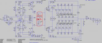
I have the amp from picture below running as prototype, but with only 1 pair off output BJT's.
Now I was wondering, would Mosfet pair K1530/J201 as drivers be soundwise better than the 10P20/10N20 LatFET's?
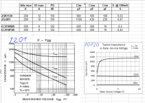
I've included the main parameters and capacitance parameters in the table.
The LatFET's give better performance, better overall THD and less high order harmonics. I know FET spice models are far from ideal, I used the cordell models for the 1530/201 and the N20/P20 models from Ian Hegglun.
Someone experience with this comparision, maybe JC?
I have the amp from picture below running as prototype, but with only 1 pair off output BJT's.
Now I was wondering, would Mosfet pair K1530/J201 as drivers be soundwise better than the 10P20/10N20 LatFET's?
I've included the main parameters and capacitance parameters in the table.
The LatFET's give better performance, better overall THD and less high order harmonics. I know FET spice models are far from ideal, I used the cordell models for the 1530/201 and the N20/P20 models from Ian Hegglun.
Someone experience with this comparision, maybe JC?
Attachments
Last edited:
- Status
- This old topic is closed. If you want to reopen this topic, contact a moderator using the "Report Post" button.
- Home
- Amplifiers
- Solid State
- mosfet driver