Hi forum
I had a discussion with an old guy ( he has been working as a radio mechanic for many years ), he claims that mosfet's with even high Ciss gives good result in audio amplifiers, just don't use high Ciss in low power amps like headphone amplifiers, he says. I think i've always heard, that we want the lowest Ciss as possible ...right ? Can IXTH16N10D2 mosfet be used for a simple source follower lets say 1 - 2 W into 8 Ohm speakers ? I want to use lamps as load and maybe 40 - 50 VDC powersupply ?
I already got a couple of these IXTH16N10D2 mosfet's, which has a very high Ciss of 5700 pF. Take a look at the datasheet, which actually tells that it can be used for Audio amplifiers !
http://ixapps.ixys.com/Datasheet/DS100258B(IXTH-TT16N10D2).pdf
Somewhere around -3V for ~4mA Drain current. Interesting devices. Would be a bit difficult to use them in a quasi output stage since it would require a 3rd rail to bias the lower. As a SE follower they would work pretty good given the right drive circuit. Given enough heatsink you could go to 10 watts or more with a pair, one as follower and one as CCS.
Last edited:
depletion can be used for audio
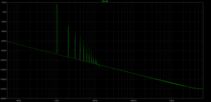
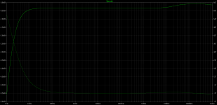
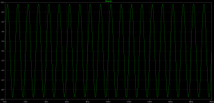
I had another depletion mosfet model (IXTT20N50D)
and driven from the low resistance source it shows indeed good performance, at ~1A idle, the files attached.
Moreover it can drive from the drain a transformer like from anode in tube amps but with significant more power.
I had another depletion mosfet model (IXTT20N50D)
and driven from the low resistance source it shows indeed good performance, at ~1A idle, the files attached.
Moreover it can drive from the drain a transformer like from anode in tube amps but with significant more power.
Attachments
Indeed OP's devices should work well in something simple. Driven from a low impedance source the following I imagine would sound pretty good after tuning the gate resistors. According to datasheet curves it should idle at ~1.5A and manage close to 6 watts into 8 ohm. OF course burning 75 watts at idle.
Attachments
You originaly asked for a small follower. Well here is one Nelson posted true C1 would probably need to be larger as this was intended as a tweeter amp so the small value adds
some added protection to the tweeter in case of a turn on thump.http://www.diyaudio.com/forums/pass-labs/265557-simple-follower.html
some added protection to the tweeter in case of a turn on thump.http://www.diyaudio.com/forums/pass-labs/265557-simple-follower.html
You originaly asked for a small follower. Well here is one Nelson posted true C1 would probably need to be larger as this was intended as a tweeter amp so the small value adds
some added protection to the tweeter in case of a turn on thump.http://www.diyaudio.com/forums/pass-labs/265557-simple-follower.html
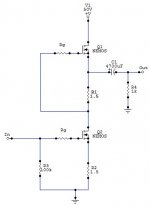
It won't work for depletion devices. Even at 0V Vgs the OP's devices will be dumping 25A+. A follower can be done as simply as my last post, moving a single resistor.
Edit: oops of course adding an input capacitor as well.
Attachments
Last edited:
jerluwoo:
That looks nice, what values should Rg have in the schematic you've done 100 ~ 470 Ohm ? Only problem is ...i only have two of those IXTH16N10D2 and for the shown ill. i need four pcs. but it looks as a simple way to make the CCS.
padamiecki:
Thanks for pointing the negative bias, for the depletion mode ( i could have made a mistake there ).
overpower:
Nice to know these depletion mode mosfets works ..thanks.
woody:
Exactly, i was going for something as simple as possible and the thought was using lamps for the load ...but i like all you guys suggestions ( so please bring all your suggestions ).
Could a follower be done as simple as the attached schematic ? You're wecome to point out something to be changed !
( crap, i've just found out that it's not possible for me to post images anymore at the host i'm normally using ).
Okay then TinyPic must be a help.
An externally hosted image should be here but it was not working when we last tested it.
Last edited:
Attachments
Hello Mr. Pass
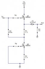
I've stolen the drawing from Michael Rothacher ( the L'amp ) and edited it. Hope it's okay
Thanks for the link, i'll take a look at it. Actually i have one of your De'Lite amp's running and i'm listening to it, right now ...and i'm very glad about the simple designs, you have done.
What value should C3 and C4 have ?
Last edited:
Yes it could be used directly in this circuit by changing R4 to 2 ohms to give the proper bias adjustment range.
C3 can be 4700 to 10000uF and C4 2.2uF.
Last edited:
Yes it could be used directly in this circuit by changing R4 to 2 ohms to give the proper bias adjustment range.
C3 can be 4700 to 10000uF and C4 2.2uF.
jerluwoo:
Thanks for the values.
I've just crancked both IXYS mosfet's up just for testing them with a lamp ....does they work ? nope ( China crap i think ...it's not first time i've bought something with wrong pinout ).
Pins should be following: G D S ( i've tried a variation, Gate and Source connected, between 100 k down to 1 k without results )
Update:
These mosfet's i have, can only open between gate and drain, which must tell it's not a IXTH16N10D2 depletion mode mosfet, even if it's what's printed on the components. Where on Ebay can i buy some "REAL GENUINE" depletion mosfet's ? Not from hkutsource it seems !!!
Sorry, but i'm really pissed of right now.
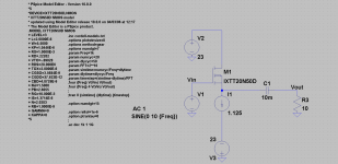
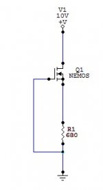
For testing them for how close they are to spec see the following attachment. According to the datasheet this should give in the range of 5-15mA across R1. 1k in the source is too much and should result in a cutoff condition.
Hi jerluwoo
First i want to say thanks for the help you're giving today.
I've just used the tutorial below and tests went out fine. Mosfets works but not as discribed ...as a depletion mode. It can only open between drain and gate.
https://www.youtube.com/watch?v=RBJGOOTEwfU
Last edited:
If testing with a meter there should be no continuity between gate and source or gate and drain. If there is any then the gate has been destroyed, probably by a static charge. Mosfets should come with the pins stuck in anti-static foam or anti-static bags. Clamping a gator clip across all 3 leads after removal of anti-static measures is always a good idea until they are soldered into place. Sorry about their untimely death. Perhaps looking to purchase them or something simular from a vendor like Mouser or Digikey instead of Ebay would be a better way to go.
Edit: Was posting while you were. Sad the horrendous issue of fakes flouding every aspect of electronics components these days.
Edit: Was posting while you were. Sad the horrendous issue of fakes flouding every aspect of electronics components these days.
Last edited:
- Status
- This old topic is closed. If you want to reopen this topic, contact a moderator using the "Report Post" button.
- Home
- Amplifiers
- Solid State
- IXTH16N10D2 for amplifier use ?