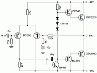
Can i use BC639 instead of BC546/BD140, and BC640 instead of BC556/BD140. BC546-556 out of stock and i can't find BD139-140 here. They are almost the same as BD139-140 in the datasheet.
gless try deeco at raon...
I'm having a problem, there is always a + or - 4.X volt in the output. Build 3 pcb, 2 from Greg Erskine and 1 from rakesh_sharma23 design. But Same result. Check and replace all transistors but still the same for the 3 pcb's.
Could it be the bias diode? I use 1N4148, can't find 1N914. But can't check if this is really 1N4148 cause there is no markings of some sort.
Could it be the bias diode? I use 1N4148, can't find 1N914. But can't check if this is really 1N4148 cause there is no markings of some sort.
I'm having a problem, there is always a + or - 4.X volt in the output. Build 3 pcb, 2 from Greg Erskine and 1 from rakesh_sharma23 design. But Same result. Check and replace all transistors but still the same for the 3 pcb's.
Could it be the bias diode? I use 1N4148, can't find 1N914. But can't check if this is really 1N4148 cause there is no markings of some sort.
Hi gless,
1N4148 and 1N914 are the same. You could try using 2 to start with.
Measure Vbe of all transistors. It may help you work out where the problem is. Check the orientation of all the transistors.
regards
I'm having a problem, there is always a + or - 4.X volt in the output. Build 3 pcb, 2 from Greg Erskine and 1 from rakesh_sharma23 design. But Same result. Check and replace all transistors but still the same for the 3 pcb's.
Could it be the bias diode? I use 1N4148, can't find 1N914. But can't check if this is really 1N4148 cause there is no markings of some sort.
Made 6 amp.. no problem found... I am using IN4148 and BD139,140 every things ok Here.. Sounds nice..
Will update pics soon...
Sorry for late reply, its now complete and working fine. Created 3 channels for 2.1 setup for my pc.
I remove all the parts and clean the pcb, bought parts from another store. First power-on and it works. Maybe the parts i bought first is are all fakes.
Great to hear that... Would like to share some pics..
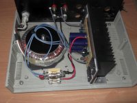
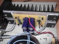
I am about to finish my 6-Channel Amp.. AMP boards are ready and tested, working on case...
Some pics...
Still not finshed yet... Tested Sounds very nice...
An externally hosted image should be here but it was not working when we last tested it.
An externally hosted image should be here but it was not working when we last tested it.
An externally hosted image should be here but it was not working when we last tested it.
Still not finshed yet... Tested Sounds very nice...
That`s nice and tidy, just remember, that m d f cabinet will act as an insulator
and the fans are likely to just re-circulate hot air.
I may be worthwhile considering moving the fans to a location at each end of
your heat-sink and at 90 degrees, cut out vent holes in the cabinet sides and mount the fans directly to the cabinet with a grill, important to have the fans, extracting air from inside the cabinet to the outside, cut a third, or fourth inlet vent, at a location (both ends is best) that causes fresh air to flow over the transformer and heat-sink, add a 75 degree self resetting N/O thermostat to the fan power lead, and attach to the heat-sink for fan operation only when required.
One fan in the center would be more than adequate. Cover all the fins to duct the air through them. Cut exhaust slots at the sides of the sink. Have an air inlet somewhere near the back. The fin profile is such that there should be some airflow at all times, a switch for high-speed fan at high-temp would be nice.
....i wonder what excuse anyone will have to comment this work as nice and tidy while a bunch of errors and some of them quite critical
--twisted cables are very wrong for such an application
--even worst if all of them tied up all together
--crosstalk figures will hit the sky
--even worst when input and output cables also tied together ( oscillation will be waiting around the corner )
--i see no decoupling anywhere in the power supply ( s)
--i wonder if any adjustments needed how they are going to be done
--I see no inductor but may be i am wrong and trust me in a six ch amp is obviously needed
nice looking job doesn't mean that is also proper ...
Thanks for feedback..
Amp is running fine..
Few problem in found are
1. Some noice can be heared when audio is muted ( May be twisted cables issue as pointed by "sakis" above) or some circuit layout design problem (Power supply in on the same board).
2. MFD Cabinet and Poor Heatsink result heating... but not too much..
Solution .. will be making new layout, Powersupply will go on saprate board..and a new cabinet and some good heatsinks..
The original design is a utility amp. i.e. for general purpose use in audio for musical instruments, monitors, desk amplifiers etc. Not hi-fi. THD is ~0.05% @ 50W/8R.
That assumes the original design parts lineup which included MJ802/4502 output transistors for 125W/4R. The remainder were all small-signal T092 transistors, BC546/56 types, including the drivers. Without decoupling, noise is largely power supply dependent, so a really well designed and built power supply is going to improve hum and noise substantially.
Here is a link to Greg Erskine's site, showing a test build on a commercial PCB with the T092 transistors.
However, I would be concerned about the use of this design for subwoofer duty which is the highest average current duty for amplifiers. I think there are better designs for woofer amps and they usually involve more output pairs for a given power rating. That means more drive current and gain too.
The design is the basis for AKSA 55 and B-AKSA. To all accounts, they sound just fine and AKSA 55 sold as an audiophile kit product internationally, so something must be good about this ultra-simple, minimum parts count design.
If you want to use 2N3055 output transistors , the simple answer is no. +/- 40V is the maximum supply allowed for them, in AB power amplifiers with 8 ohm loads. +/-35V would be considered a safe maximum for hard use with lower impedance loads. The rail (+/-power supply) limits are set by the transistor Vceo and output voltage level. It has little to do with amplifier design or bias resistors, though it may be wise to change a few values in more complex Vbe multiplier designs.Hi, can this circuit operate at +/-45V or do I need to increase the values of the bias resistors? ...
The alternative is to upgrade the transistors to higher voltage and current types suited for the 100W/8R or even more, that may be possible with 45V rails. The amplifier was originally specified for 125W/4R as stated earlier, so all components would have to be assessed for uprating to suit the increased voltages and currents.
Looking at rakesh's transformer though, I would not be surprised that its regulation was poor enough to allow the rails to sag well below 40V at maximum power. If you find one like that, it might save your transistors - or it might not
The Digi125 was in fact my start point for the AKSA.
I heard this amp in 2000 for the first time and was impressed with the sound for such a simple, elegant circuit. I resolved to refine it more, and in just a few weeks had the first prototype of the AKSA 55, which sold in hundreds as a kit.
During the development I spent time on the choice and dimensioning of all components. And since I did not have an Audio Precision 2, and no intention to buy one, I did long term listening tests with many friends, audiophiles, and lots of different music.
I commend this design, the designer, Graham Dicker, is a very, very clever man.
Hugh
- Status
- This old topic is closed. If you want to reopen this topic, contact a moderator using the "Report Post" button.
- Home
- Amplifiers
- Solid State
- DIGI-125 Kit Amplifier Module


