I would say so. Anywhere from 30v dc to 50 like somebody else I know of, will work. Just remember the changes I recomended, an extra diode, BF469 in Q3 with 68pF cap for C2 and the Toshiba 2SC5200/2SA1943 outputs on Q6 & Q7. You can download the schematic on the previous page and get the boards from RCS. You will find it all in the previous correspondence.
And, don't forget to post your impressions here for others to see!
Cheers,
tomcat
And, don't forget to post your impressions here for others to see!
Cheers,
tomcat
This is a very old thread, but I wanted to mention that the digi125
will give impressive results when the motorola MJ802 MJ4502 outpud devices are used in place of the standard drivers and configure four of the digi125`s as bridged pairs, I built this amp around fifteen years ago and it has given stunning performance without any of the high frequency instability that can affect the amp when constructrd in its default configuration. Its driving a single pair of three way speaker cabinets with fifteen inch drivers,
and sounds transparent but if needed (parties or whatever) I can ramp it up, actually the room on the opposite side of the wall the speakers are in front of has to have the pictures taken down or they get blown off
Wow! this brings back memories.
I've got the original ETI magazine featuring the DIGI-125, bought when I was a high school student.
Sorry to say it, but it really isn't a good design. Class B operation of the output devices and TO-92's as drivers for the low fT TO3 outputs! The whole thing was also packed on a tiny circuit board with really narrow tracks for the high current paths.
I think the ETI-480 with the four output device option is a better design than this.
jaya000 said:Toshiba 2SC5200/2SA1943 or motorola MJ802 MJ4502?
Which will be better?
I used Toshiba 2SC5200/2SA1943.
regards
Attachments
G.Kleinschmidt said:Wow! this brings back memories.
I've got the original ETI magazine featuring the DIGI-125, bought when I was a high school student.
Sorry to say it, but it really isn't a good design. Class B operation of the output devices and TO-92's as drivers for the low fT TO3 outputs! The whole thing was also packed on a tiny circuit board with really narrow tracks for the high current paths.
I think the ETI-480 with the four output device option is a better design than this.
Hi Glen,
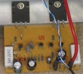
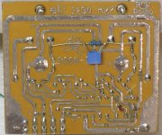
I'm not sure if this PCB is close to the original, but on 25VDC rails I found the VAS transitors to be the one to worry about heat wise.
I was surprised, with a few mods, this simple amp sounded quite good. I preferred it to the Gainclones I was builting at the time. It definitely responded well to a little more bias and a bootstrap on the VAS.
BTW: The power traces are quite thin as you mentioned.
regards
Attachments
Give details about what mod u did.I was surprised, with a few mods, this simple amp sounded quite good. I preferred it to the Gainclones I was builting at the time. It definitely responded well to a little more bias and a bootstrap on the VAS.
Preferably schematics.
The digi125 is a class A amplifier, confirmed when I contacted the designer Graham Dicker.
He sent me instructions with the last batch of boards I purchased last year, for a 200watt version which uses the MJ15003/004 devices, however in this form the Amp is in class B operation.
If anyone wants the instruction I can post them here.
He sent me instructions with the last batch of boards I purchased last year, for a 200watt version which uses the MJ15003/004 devices, however in this form the Amp is in class B operation.
If anyone wants the instruction I can post them here.
Based on the posted schematic, this amp has rather undefined bias, which is likely class B or could even be said it's class C depending on what transistors one uses. The 'floating base' darlingtons do not inspire confidence either.
There is a quote attributed to Alber Einstein: Things should be as simple as possible, but no simpler. Well, it seems to me this amplifier attempts to be simpler.
There is a quote attributed to Alber Einstein: Things should be as simple as possible, but no simpler. Well, it seems to me this amplifier attempts to be simpler.
Muff said:The digi125 is a class A amplifier, confirmed when I contacted the designer Graham Dicker.
Hi Muff,
The standard Digi125 is definitely not a class A amplifier. With only 2 diodes for bias it is lucky to get warm.
Are you referring to a different or modified amp?
regards
"He sent me instructions with the last batch of boards I purchased last year, for a 200watt version which uses the MJ15003/004 devices, however in this form the Amp is in class B operation."
Aussie watts?
I might believe it with a huge supply for a very, very, short time before the magic smoke is let out.
The Peavey CS400s used three pair on ±57V with a healthy transformer for 200W/4R.
I built some Pass A40 boards driving three pair of MJ15015/16 on ±57V that still run (after almost 30 years). The amp had two small transformers (~200VA) and did 200W/4R, with two 15,000µF per channel.
The A40 boards are still available for $6 from AudioXpress.
Greg Erskine said:
Hi Muff,
The standard Digi125 is definitely not a class A amplifier. With only 2 diodes for bias it is lucky to get warm.
Are you referring to a different or modified amp?
regards
Well now I`m a little confused I have to confess, I thought in class b operation, there is no forward bias, therefore no quiescent current flows i.e. the output devices are not turned on, in the digi125 the quiescent current is around 40ma provided by the two diodes.
in the digi125 the quiescent current is around 40ma provided by the two diodes.
No, not!
The diodes are providing 0.7+0.7=1.4V bias. The EF stage (drivers+ouputs) needs 2.2...2.4V.
So the bias current in the Digi125 is almost zero.
Not all diodes drop the standard 0.7v. This value is only a convenience to make calculations easier.
The volt drop or Vf is dependent on the current flowing. Its not like a resistor; the Vf/If graph is not linear and Vf is not a constant for all values of If.
The 1N914 for instance has a Vf of 1v at 10mA forward current whereas the 1N400x series have a Vf of 0.7v at an If of 10mA and reaches 1v Vf at 1A If! Different types of diodes will have less or greater forward voltages. Similarly the transistor Base Emitter diode Vf is not a constant 0.7v for all types of transistors! This again depends upon the current flowing through the BE diode and can be lower than the assumed 0.7v. Actual values can be obtained from datasheets.
So long as the forward current is a constant the Vf will depend upon this current but also the ambient temperature which is why diodes are used to give a small temperature compensation.
I hope I have explained this OK.
Tony.
djk said:"He sent me instructions with the last batch of boards I purchased last year, for a 200watt version which uses the MJ15003/004 devices, however in this form the Amp is in class B operation."
Aussie watts?
I might believe it with a huge supply for a very, very, short time before the magic smoke is let out.
The Peavey CS400s used three pair on ±57V with a healthy transformer for 200W/4R.
I built some Pass A40 boards driving three pair of MJ15015/16 on ±57V that still run (after almost 30 years). The amp had two small transformers (~200VA) and did 200W/4R, with two 15,000µF per channel.
The A40 boards are still available for $6 from AudioXpress.
Ok here are the instructions I was given for the 200watt version by the author, I am quoting verbatim.
================================================
Digi-200 modifications
The secret to modifying the digi125 amplifier to produce 200 watts RMS into 2 ohms lies in some basic improvements to the thermal design of the module.
Normally to produce levels of this amount one would expect to find two pairs of MJ15003/004 devices in the output stage, the main reason being to ensure the 50A (Safe Operating Area) of the output devices are not exceeded. We are able to obtain 200 watts from a pair of devices and still remain inside the 50A by using two design techniques. (1) by using low power supply rails with a low load impedance. (2) by using good design practice with regard for the thermal consideration.
Instead of mounting the module to a small aluminum bracket and then to a heatsink we now mount the PCB and output transistors directly to a heatsink, this lowers the thermal resistance to air and improves the heatsink efficiency. Thus enabling us to use only one pair of output devices. A large heatsink with a low thermal resistance such as a DSE H3472 or a Jaycar MF-21-1F-75 with a thermal resistance to air of .6 deg/c/watt is recommended.
The changes required are to insert a wire link in the PCB in place of R7 and R8 (As the output devices are not turned on i.e. they are in class B no quiescent current flows . This also improves the damping factor ( lowers the output impedance of the output stage.).
Q6 is changed for a MJ15003 and Q7 for a MJ15004. R6 must be a proper 1/2 watt resistor.
For increased voltage gain (av=50 instead of av=20) R4 can be reduced in value to 2K2.
In the schematic diagram Q4 should be a BC556 R3 and R2 should be 4K7.
================================================
At the end of the day I like what sounds good, I was in hifi retail for a few years and saw some nice equipment, in those years, but I would not part with my digi125 based amp for anything.
I built it 20 years ago and to date has never had any sort of failure, things only go pop and fizz when the wrong sort of load is driven or the amp has poor thermal characteristics or a combination of the two.
My implementation of the digi125 is four modules in bridged pairs,
for a two channel output. The power supply x4 are based on a 25-0-25 volt 300VA toroid and a bank of 8 caps, per module, You have to build one of these and set it up properly to appreciate how incredibly transparent they sound along with vast amounts of power
if needed and for hours at a time without any thermal problems.
Im not familiar with Aussie watts
but I know what a sound pressure wave feels like Not all diodes drop the standard 0.7v. This value is only a convenience to make calculations easier.
The volt drop or Vf is dependent on the current flowing. Its not like a resistor; the Vf/If graph is not linear and Vf is not a constant for all values of If.
The 1N914 for instance has a Vf of 1v at 10mA forward current whereas the 1N400x series have a Vf of 0.7v at an If of 10mA and reaches 1v Vf at 1A If! Different types of diodes will have less or greater forward voltages. Similarly the transistor Base Emitter diode Vf is not a constant 0.7v for all types of transistors! This again depends upon the current flowing through the BE diode and can be lower than the assumed 0.7v. Actual values can be obtained from datasheets.
Thanks, but I'm into amplifier designing since many-many years, I already know these!
The current flowing through the bias diodes at 38V rails ~17mA. At this current an 1N914 drops ~0.78V. Then the total bias voltage is 1.5...1.6V. Still not enough for a darlington-EF OP stage (2.2...2.4V needed as I wrote it before)!
Check datasheet, at 10mA If an 1N914 drops ~0.72V. Not 1V as you wrote!The 1N914 for instance has a Vf of 1v at 10mA forward current
Andy L. Francis said:
Check datasheet, at 10mA If an 1N914 drops ~0.72V. Not 1V as you wrote!
You were obviously looking at a different manufacturer's datasheet to me.
Tony

Greg Erskine said:
Hi Glen,
I'm not sure if this PCB is close to the original, but on 25VDC rails I found the VAS transitors to be the one to worry about heat wise.
I was surprised, with a few mods, this simple amp sounded quite good. I preferred it to the Gainclones I was builting at the time. It definitely responded well to a little more bias and a bootstrap on the VAS.
BTW: The power traces are quite thin as you mentioned.
regards
This is the original ETI-1430 board from Graham Dicker.
The image is actual size.
An externally hosted image should be here but it was not working when we last tested it.
- Status
- This old topic is closed. If you want to reopen this topic, contact a moderator using the "Report Post" button.
- Home
- Amplifiers
- Solid State
- DIGI-125 Kit Amplifier Module