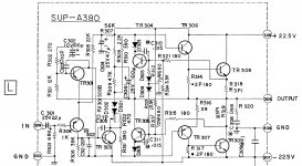
Hello can you please help me to add a Baxandall transdiode or diode across R139 or (may be better) across R316 without doing a disaster?
The amplifier is National Panasonic SA-73 (1971)
1) Is it better a power diode across R319 (1 Ohm) or a transdiode across R366 (39 ohm)
2) Can I add directly in parallel or I have to change any components, like rise R316 equal to R317 (180 ohm)? Which resistor value in parallel?
3) Should I have to add a few nF capacitor in parallel ?
4) Which diode/transistor type do you suggest (see below cross ref)? I would like to maintain a vintage configuration so i need to add components exsisting in the seventies
5) What voltage/bias level I should read to be sure that everything works, after adding the Baxandall?
Legenda:
R318, R319: 1 ohm
R314,R317: 180 ohm
R316: 39 ohm
R306 (wrong): 3K9 ohm
TR308,309: 2SD154
TR306: 2SC853
TR307: 2SA545
TR301,302: A2SA564
TR303: CS1383
TR304: 2SC828
all diodes: DS410
PS: I'm trying to simulate with MicroCAP: the problem are the missing models. May be:
2SC853 == BC639 ??
2SA545 == BC640 ??
2SD154 == BD241B, 2N3054 ??
2SA564 == BC213, BC308, BC558 ??
S1383 == 2N4919, 2N4236 ??
DS410 == 1N4148 ??
2SC828 == BC183, BC238, BC548 ??
PS: According to:
http://ochtedete.free.fr/!-amplis/quasi/QuasiComp/QuasiComp.PDF
I should add a 10nF~22nF parallel capacitor but I cannot see the pic here...
Attachments
Last edited:
A diode across R316 would be the correct location for a "Baxandall Diode" and using a general purpose device such as 1n4001. I wouldn't like to say whether the resistor should be tweaked or not. Typically you might see nearer 100 ohm here... one to simulate ")
(models in simulation probably have only a minor effect of what you are looking at, just use generic common devices)
(models in simulation probably have only a minor effect of what you are looking at, just use generic common devices)
While on this subject, I'd like to point out that neither Shaw nor Baxandall actually invented that circuit modification, as their articles are dated 1968/69, if I'm not mistaken. The Scott Stereomaster 342 / 382 receiver, released in 1965, already had that circuit.
Probably Baxandall and Shaw were the first to actually analyse and divulgate that modification to the technical public.
Probably Baxandall and Shaw were the first to actually analyse and divulgate that modification to the technical public.
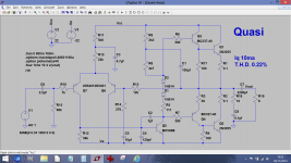
The Quasi output stage only occurs at the two NPN devices.
Prior to that the amp is complementary.
What the diode/capacitor/resistor do is ensure the NPN and PNP driver transistors see equal loading on their emitters.
The sch shows the NPN driver emitter loaded with R314||baseTR308
That base looks like a diode and a capacitor in parallel. The effective load on the NPN driver is R314||diode||capacitor.
Now look at the PNP driver.
It is loaded with R316, nothing else.
The parallel effect of the output transistor is missing.
That's where the Shaw and Baxandall modifications come in.
One ADDS the parallel loads to TR307's emitter to mimic what TR306 sees.
Once you see that, you know where to put the added C & D, in parallel to R316.
However, we are not finished.
The two NPN transistors are not loaded equally.
TR308 has an emitter resistor, TR309 has none. Three little piggies went to market.
Add an emitter resistor to TR309.
Now compare the upper combination R314 TR308 R318 arrangement to the lower side, R317 TR309, Re.
Last edited:
One of the problems I forsee with this amp (modifying it) is that the bias stability may suffer.
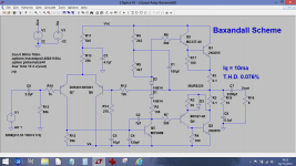
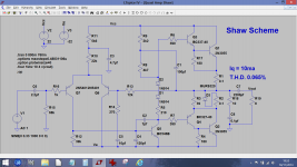
I would tend to disagree with Andrew about adding an emitter resistor too. The "Shaw" scheme would add the diode in series with R319 and with the emitter of the driver trasistor being returned to the collector of TR309 and not the output line as it is now. You would still bypass the diode and collector resistor with the 39 ohm, perhaps making that a bit higher.
The Baxandall scheme adds a series diode to the driver transistor emitter. This would probably also be returned to the collector of TR309 rather than the output line. The diode could also be bypassed with a resistor and small cap.
What you do to the lower driver as regards its emitter connetion you do to the top, so that means transferring R314 from its present location to being simply across base-emitter of TR309.
(it is an ideal candidate to simulate actually... you could have a lot o fun trying the various configurations out)
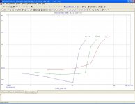
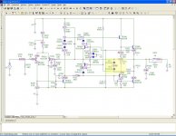
The three schemes, Quasi, Baxandall and Shaw. Values carried over from your circuit and not optimised. Iq set to 10 ma for all three. I've written the T.H.D. on each image. Output was at 10.5 volts RMS 1kHz. This was the max swing available before asymmetric clipping on the negative side.
Enjoy
Enjoy
Attachments
Hi,
I like the Baxandall scheme more than the Shaw, its just
a lot more practical in terms of the diode used, and allows
you to adjust R3 more usefully I'd suggest than Shaw.
TBH I'm not too sure the examples shown by Mooly actually apply to
the original circuit, and without a lot of further investigation of the
Panasonic circuit AFAICT a diode won't help. It already has a
symmetric loop that probably addresses the problem, or not,
I can't be sure, but cannot see the simple cases Mooly shows.
FWIW I really don't like the schematic, its very confusing.
rgds, sreten.
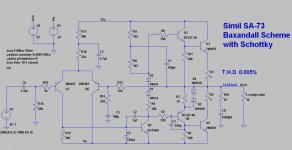
Two Baxandall Schottky ??
Hi, many many thanks for the LTspice models.
Improvements are really visible!
There are few components uncorrect, so I redesigned it according to original schematic.
After many simulations I found:
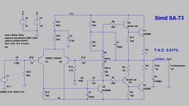
1) original = 0.017% THD
2) with Baxandall diode (added 100 pf Cap, as suggested) = 0,007% THD
3) with two serie Schottky = 0.005% THD
4) optimised R316 resistor = 47 ohm (no big change THD, so I will stay with original 39 value)
5) a transdiode is performing worse than the diode
What do you think about two serie Schottky ?
Hi, many many thanks for the LTspice models.
Improvements are really visible!
There are few components uncorrect, so I redesigned it according to original schematic.
After many simulations I found:
1) original = 0.017% THD
2) with Baxandall diode (added 100 pf Cap, as suggested) = 0,007% THD
3) with two serie Schottky = 0.005% THD
4) optimised R316 resistor = 47 ohm (no big change THD, so I will stay with original 39 value)
5) a transdiode is performing worse than the diode
What do you think about two serie Schottky ?
Attachments
That's interesting. I see I read the 3k9 off the diagram as 39k. That will make a difference, lol, its a wonder it ran actually. The output stage resistors are 1 ohm ! That sounds more reasonable. Changing those has lowered Iq a little on the sim. Bring it back to 10ma and distortion falls a little more. The double diode seems to work well enough.
Are you going to try it for real ?
Are you going to try it for real ?
Thanks for drawing all this out Mooly & Ygg-it, and for the panasonic SU380 source schematic. The text version of the Bauxendall and Shaw mods was way over my head.
I've just built the quasi comp Pwg-Tang modification to ths dynaco ST120 driver board, http://www.diyaudio.com/forums/solid-state/53053-dynaco-st-120-a.html
On Nema C laminate, and find it is fixed bias 380 ma whatever the position of the bias pot is. That is worse than the defective djoffe feedback bias circuit I am replacing which with the current mirror broken was putting out 220 ma bias current. Fortunately the fans I added took care of the heat.
I've been modding Pwg Tang one part at a time to the Apex AX6 and find I've got 480 ma bias at this point, with pnp driver emiter resistor changed from dynaco 3.3 ohm to AX6 33 (his 27 ohm) , and an output transistor emitter 0.5 ohm resistor added. It is lighting the AC light bulb pretty bright after the 33 ohm mod.
By deleting the feedback transistor, replacing it with a speaker capacitor, and feedback through an emitter resistor on the input transistor, (Original ST120and Pwg-Tang circuit) I think I can manage to fit this output stage on my board. At last, some modern ideas about quasi-comp.
I'm in a bland mid-western Spice free zone, all my Windows op systems get destroyed by microsoft since nobody will give me or sell me the source disk with these used computers. Lubuntu op system has an electronic layout feature, but no simulations. Back to the soldering iron. Next trial is changing the npn driver pull up resistor from dynaco 1.5 kohm to AX6 3.3 kohm.
Last edited:
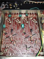
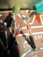
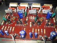
As you may see from the attached photo, I have installed with success a fast diode (BYX55) and a 68pF capacitor across CB on Q4.
I've chosen this just beacause it existed in 1971.
From a technical point of view (I have connected the ampli to my soundcard and measured THD), I don't see any difference at low levels, and just a tiny reduction of the third harmonic close to clipping, in favour of the second harmonic distortion.
From a listening point of view the sound is much clear and less fatiguing overall at the highest frequencies, but I'm not sure if this feeling is just a Placebo effect.......
In any case I will keep it, since I don't see anything contrary.
Just a favour: can you please provide a BYX55-600 LTspice model?
Attachments
Last edited:
From a listening point of view the sound is much clear and less fatiguing overall at the highest frequencies, but I'm not sure if this feeling is just a Placebo effect.......
Live with the mod for a few days/weeks/months. If it consistently pleases then it was worthwhile.
Just a favour: can you please provide a BYX55-600 LTspice model?
Just like that
You could either do your own model
or ask over at the LTSpice users group on Yahoo. The BYX55 was an old favourite for TV repair.Just for interest, have you tried using things like a IN4148 model and say a 1N4001 and seeing whether there is any real difference in the final results.
On Semi's versions of 1N4933-37 would seem comparable in reverse recovery to BYX55/350-600. At least they are cheap, still in production and you can obtain spice model data online. http://www.onsemi.com/pub/Collateral/1N4933-D.PDF
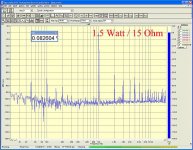
Made interesting variants and improvements.
A colleague suggested me to pass from LTspice to MicroCap, since it provides a complete and reliable THD% analysis, very natural front-end and a lot of components to choose.
So we redrew the entire circuit, using cross-referenced components and we did many Bandaxall simulations using only vintage components in order to avoid anachronistic mistakes.
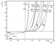
Typically, a silicon diode has a VF around 0.6-1V. Two Schottky diodes performed better on the simulator: they are much faster and have a lower forward voltage (0.2V), but Schottky were not accessible on the market during 1971.
A germanium diode, which was regularly used in the early seventies, has a VF similar to Schottky diodes, is fast enough and has VF around 0.3V
So we modelled two 1S188 germanium diodes in series (VF doubled to 0.6V) using the 1N34 model:
*1N34A MCE
* 60V 85mA 100ns Ge Signal Diode pkg : DO-41 1,2
.MODEL D1N34A D(bv=75 cjo=0.5e-12 eg=0.67 ibv=18e-3
+ is=2e-7 rs=7 n=1.3 vj=0.1 m=0.27 )
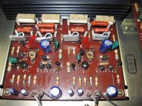
In order to get the lowest THD%, we increased R316 from 39 to 47 ohm, in parallel to the diodes.
Finally two 1S188 germanium diodes in series performed better both on the simulator, on the measurements and during listening test, than a single BYX55 fast silicon diode.
(PS: the amplifier has been totally recapped too using Panasonic cap)
A colleague suggested me to pass from LTspice to MicroCap, since it provides a complete and reliable THD% analysis, very natural front-end and a lot of components to choose.
So we redrew the entire circuit, using cross-referenced components and we did many Bandaxall simulations using only vintage components in order to avoid anachronistic mistakes.
Typically, a silicon diode has a VF around 0.6-1V. Two Schottky diodes performed better on the simulator: they are much faster and have a lower forward voltage (0.2V), but Schottky were not accessible on the market during 1971.
A germanium diode, which was regularly used in the early seventies, has a VF similar to Schottky diodes, is fast enough and has VF around 0.3V
So we modelled two 1S188 germanium diodes in series (VF doubled to 0.6V) using the 1N34 model:
*1N34A MCE
* 60V 85mA 100ns Ge Signal Diode pkg : DO-41 1,2
.MODEL D1N34A D(bv=75 cjo=0.5e-12 eg=0.67 ibv=18e-3
+ is=2e-7 rs=7 n=1.3 vj=0.1 m=0.27 )
In order to get the lowest THD%, we increased R316 from 39 to 47 ohm, in parallel to the diodes.
Finally two 1S188 germanium diodes in series performed better both on the simulator, on the measurements and during listening test, than a single BYX55 fast silicon diode.
(PS: the amplifier has been totally recapped too using Panasonic cap)
Attachments
Bring National Panasonic SA-73 to second life
SUMMARY
At last I finished to restore the National Panasonic SA-73 (1971), vintage integrated amplifier purchased on second hand already in nearly mint condition.
National was a brand used by Panasonic Corporation (formerly Matsushita Electric Industrial Co., Ltd.); in early 80s Matsushita ceased the usage of "National" brand, and sold audiovisual products exclusively under the Panasonic and Technics nameplates.
Since the beginning this amplifier played so fine in my system, that it soon replaced directly my Class A Musical Fidelity A120 (1990) which I have used for many years. That is the reality!
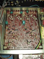
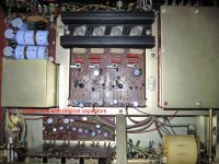
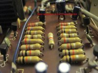
From the photos and schematic I got from different SA73 machines, the amplifier was issued at least in four minor electrical variants, all in the power stage. Thus I understood that the machine which I own had preceded all the revisions made by Matsushita, that later “bodged” few extra components on the bottoms of the PCB.
Then someone of the forum has complained about the lack of the Bandaxall diode in the quasi-complementary output stage (the modification is dated 1969-70, even if already introduced before in 1965 on the HH Scott Stereomaster 342), while many folks suggested to replace all the electrolytic capacitors after more than 40 years of service.
Thanks to the experts in this forum I have brought the National Panasonic SA73 to a second life making the following (improvements) by:
a) adding two resistors (R323, R324) in the short protection circuit according to a later revision by Matsushita, in order to increase the current output of the amplifier before protection cuts in.
b) moving C312 capacitor back to the base/emitter of TR303, according to a later revision by the manufacturer, to form a classic hi-frequency compensation in the input stage which, combined to the C305 Miller capacitor, improves overall stability
c) reducing the PNP base bias resistor R303 from 100K to 68K ohm as per the latest manufacturer’s revision, to create larger current-flow through TR302
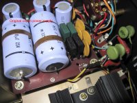
d) applying Baxandall modification across the emitter resistor of the PNP driver to improve the symmetry of the quasi-complementary output stage, with the adaptation here of germanium type diodes and increasing a little the value of the emitter resistor R316. The two germanium diodes in series should match the VBE of the upper NPN silicon driver stage. A 68 pF capacitor across base/collector of the PNP driver has been added to prevent oscillations on the output, as suggested.
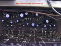
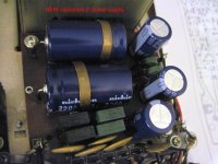
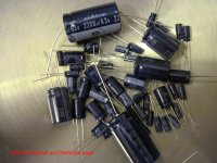
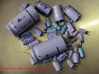
e) replacing all the electrolytic capacitors, using Panasonic brand (Nichicon Japanese brand as a second choice) and maintaining identical capacitance and dielectric as original, in order to preserve the genuine sound.
Electrolytic caps may dry or stop working since they have a limited operative life, and, I have to admit, it was not an easy decision to replace or not, because this 43-years-old Panasonic amp worked fine with all the original caps. In vintage machines “originality” affects the value somewhat, which would be fine for a museum piece, but since I was planning to use it every day, at the end I decided to replace anyhow all electrolytic capacitors in order to prevent faults.
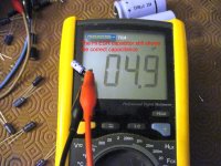
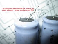
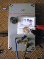
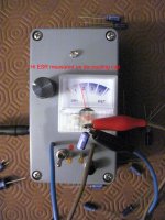
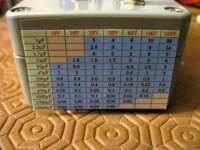
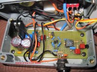
I was in any case curious to check the genuine capacitors, once desoldered. I already owned a digital capacimeter but nothing measuring ESR. So I built an ESR meter capacitor to measure ESR by comparing the 100kHz current across a suspect capacitor with the one across a good capacitor with a low ohm resistor in series. I measured that:
1) 100% of the original electrolytic capacitors have maintained the initial capacitance
2) all capacitors, except two decoupling (C304), show ESR equal to the brand-new capacitors
3) all capacitors, except one filter in power supply, have no visible effect of leakage.
What I found after 43 years was unbelievable and proves again the quality of Matsushita brand.
I hope you can enjoy all these modifications, especially if you are still a lucky owner of the National Panasonic SA73.
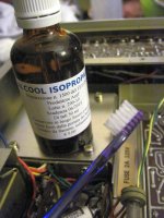
As a final point, I performed manual cleaning with brush and isopropyl alcohol and adjusted the bias current for the minimum IMD % using 19kHz+20kHz tones at the lowest volume levels.
SUMMARY
At last I finished to restore the National Panasonic SA-73 (1971), vintage integrated amplifier purchased on second hand already in nearly mint condition.
National was a brand used by Panasonic Corporation (formerly Matsushita Electric Industrial Co., Ltd.); in early 80s Matsushita ceased the usage of "National" brand, and sold audiovisual products exclusively under the Panasonic and Technics nameplates.
Since the beginning this amplifier played so fine in my system, that it soon replaced directly my Class A Musical Fidelity A120 (1990) which I have used for many years. That is the reality!
From the photos and schematic I got from different SA73 machines, the amplifier was issued at least in four minor electrical variants, all in the power stage. Thus I understood that the machine which I own had preceded all the revisions made by Matsushita, that later “bodged” few extra components on the bottoms of the PCB.
Then someone of the forum has complained about the lack of the Bandaxall diode in the quasi-complementary output stage (the modification is dated 1969-70, even if already introduced before in 1965 on the HH Scott Stereomaster 342), while many folks suggested to replace all the electrolytic capacitors after more than 40 years of service.
Thanks to the experts in this forum I have brought the National Panasonic SA73 to a second life making the following (improvements) by:
a) adding two resistors (R323, R324) in the short protection circuit according to a later revision by Matsushita, in order to increase the current output of the amplifier before protection cuts in.
b) moving C312 capacitor back to the base/emitter of TR303, according to a later revision by the manufacturer, to form a classic hi-frequency compensation in the input stage which, combined to the C305 Miller capacitor, improves overall stability
c) reducing the PNP base bias resistor R303 from 100K to 68K ohm as per the latest manufacturer’s revision, to create larger current-flow through TR302
d) applying Baxandall modification across the emitter resistor of the PNP driver to improve the symmetry of the quasi-complementary output stage, with the adaptation here of germanium type diodes and increasing a little the value of the emitter resistor R316. The two germanium diodes in series should match the VBE of the upper NPN silicon driver stage. A 68 pF capacitor across base/collector of the PNP driver has been added to prevent oscillations on the output, as suggested.
e) replacing all the electrolytic capacitors, using Panasonic brand (Nichicon Japanese brand as a second choice) and maintaining identical capacitance and dielectric as original, in order to preserve the genuine sound.
Electrolytic caps may dry or stop working since they have a limited operative life, and, I have to admit, it was not an easy decision to replace or not, because this 43-years-old Panasonic amp worked fine with all the original caps. In vintage machines “originality” affects the value somewhat, which would be fine for a museum piece, but since I was planning to use it every day, at the end I decided to replace anyhow all electrolytic capacitors in order to prevent faults.
I was in any case curious to check the genuine capacitors, once desoldered. I already owned a digital capacimeter but nothing measuring ESR. So I built an ESR meter capacitor to measure ESR by comparing the 100kHz current across a suspect capacitor with the one across a good capacitor with a low ohm resistor in series. I measured that:
1) 100% of the original electrolytic capacitors have maintained the initial capacitance
2) all capacitors, except two decoupling (C304), show ESR equal to the brand-new capacitors
3) all capacitors, except one filter in power supply, have no visible effect of leakage.
What I found after 43 years was unbelievable and proves again the quality of Matsushita brand.
I hope you can enjoy all these modifications, especially if you are still a lucky owner of the National Panasonic SA73.
As a final point, I performed manual cleaning with brush and isopropyl alcohol and adjusted the bias current for the minimum IMD % using 19kHz+20kHz tones at the lowest volume levels.
Attachments
-
 IMG_0146.JPG160.6 KB · Views: 167
 -
 IMG_0136.jpg150.6 KB · Views: 115
 -
 IMG_0112.jpg171.3 KB · Views: 116
 -
 IMG_0097.jpg188.9 KB · Views: 102
 -
 IMG_0086.jpg83.6 KB · Views: 120
 -
 IMG_0082.jpg167.6 KB · Views: 128
 -
 IMG_0078.jpg163.1 KB · Views: 117
 -
 IMG_0050.jpg176.9 KB · Views: 120
 -
 IMG_0038.jpg198 KB · Views: 135
 -
 IMG_0031.jpg152.5 KB · Views: 160
- Status
- This old topic is closed. If you want to reopen this topic, contact a moderator using the "Report Post" button.
- Home
- Amplifiers
- Solid State
- Help in design: adding a Baxandall diode across emitter in Quasi Complimentary Stage