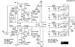
Hi Antoinel. The scheme will work, but with large nonlinear distortion. To achieve super audio only need a repeater class A. However, it is expensive. Not all have the opportunity to build such a device. Additionally, to achieve the super sound of the necessary Converter current voltage with galvanic output and powered by rechargeable batteries.Hello FEDOSOFF. The image shows a schematic of your differential 'improved current source" with modifications so as to possibly convert it to a Class A power amp; right there, and not wait to do it several steps downrange.
1. I increased the current transfer ratio [to the power output bjts] by a factor of 100:1
2. I used a voltage step down output transformer to couple power output to a loudspeaker.
3. I assumed one can do a "digital volume control" inside the DAC before its L+ and L- outputs are released to the outside world
Is this a viable option?
Best regards.
3.
Сheme Circlotron change. To improve the linearity of the output stage, the scheme introduced feedback voltage. The introduction of OS in the target cascade makes the system more resistant to accidental change of settings. The OS will expand the audio bandwidth of the output stage. Reduces the output resistance will reduce the supply noise, increase the linearity. Additionally, the linearity of the repeater increases the output stage of Sziklai. Scheme Circlotron with transformer connection becomes more universal.
Attachments
Hi Antoinel. The scheme will work, but with large nonlinear distortion. To achieve super audio only need a repeater class A. However, it is expensive. Not all have the opportunity to build such a device. Additionally, to achieve the super sound of the necessary Converter current voltage with galvanic output and powered by rechargeable batteries.
Thanks FEDOSOFF.
Hello UltimateX86. Do the symbols DA1 and DA2 in your schematic mean a DAC like shown in FEDOSOFF's schematics?.Maybe like this
Best regards
Scheme Circlotron change. . Scheme Circlotron capacitively coupled communication becomes more universal.Hi
il is not possible to made the same scheme without transformer ?
Attachments
One of the options. Hybrid driver. A single cascade is possible to capture feedback. At no dynamic distortion. To drive you need two such cascade. A single signal to be submitted to different inputs.
Hello FEDOSOFF. I hope that you are well. The voltage at the plate of vac tube is 260 V at idle. How is this value guaranteed to be constant?; noting that it may easily float [up or down] to other values so as to either saturate the transistor or depress the voltage of the plate by maximizing the collector-base voltage of transistor?
Best regards.
Hello colleagues. The Hybrid driver is adjusted. To drive you need two such cascade. A single signal to be submitted to different inputs. Dynamic resistance for the lamp - R 7.5 mW. The application of a low voltage transistor CTA ( IR-b=60 max) justified its high gain.Higher resistance is less nonlinear. Driver circuitry will be diluted in this way. Rэкв. 7,5 Mego Ohms. If you want more, add LEDs and recalculate R5.Hello FEDOSOFF. I hope that you are well. The voltage at the plate of vac tube is 260 V at idle. How is this value guaranteed to be constant?; noting that it may easily float [up or down] to other values so as to either saturate the transistor or depress the voltage of the plate by maximizing the collector-base voltage of transistor? Best regards.
Attachments
- Status
- This old topic is closed. If you want to reopen this topic, contact a moderator using the "Report Post" button.
- Home
- Amplifiers
- Solid State
- Circlotron on field-effect transistors with a stabilization system modes.