Is there an interrupt and a corresponding handling routine procedure on the Anduinos? We use to do Non Maskable interrupts on main frames for power and associated failures. In a universe far far away. It was handled fast by sub nano second logic.
This is progressing very good, lots of experienced people sharing and some like me learning something new.
This is progressing very good, lots of experienced people sharing and some like me learning something new.
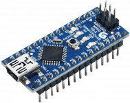
That's fine. However, some Chinese Arduino clones, have got 2 additional pins at the top, having not 30, but 32 pins in total. My schematic and layout use this pinout for compatibility reasons - I use this 32-pin clone myself.
I can create that 32 pin one if you like, it is as easy as π . The pi symbol does not come out well in the font used for display.
I don't like fans either but sometimes they are a necessary evil. My theater amps are in a closet that gets too warm. I'm thinking of building liquid cooled amps with glycol pumps. Pretty much the same control circuitry would be required. I would just need to figure out how to control return coolant temperature so I don't get condensation.
Is there an interrupt and a corresponding handling routine procedure on the Anduinos? We use to do Non Maskable interrupts on main frames for power and associated failures. In a universe far far away. It was handled fast by sub nano second logic.
This is progressing very good, lots of experienced people sharing and some like me learning something new.
Yes, Arduino allows linking individual interrupt handlers to 2 hardware pins and I use them for processing DC Offset and Current Overload alerts - the most "evil" ones, requiring the fastest reaction possible...
Plus analog acceleration for DC Offset

I can create that 32 pin one if you like, it is as easy as π . The pi symbol does not come out well in the font used for display.
Yes, this is just convenient - one can use either option
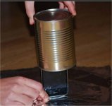
I'm thinking about the mixing of analog/digital circuitry. Will the Arduino clock
be a issue inside a tightly packed analog amp chassis ?
Will I have to put it in a faraday cage (below) ?
In the HK990 receiver I repaired , DAC's and protection were all enclosed
with tin plated steel box with a copper lining.
OS
be a issue inside a tightly packed analog amp chassis ?
Will I have to put it in a faraday cage (below) ?
In the HK990 receiver I repaired , DAC's and protection were all enclosed
with tin plated steel box with a copper lining.
OS
Attachments
I'm not sure if it would be an issue but I've been laying out my amp so there's no high current near it. Do you want one of these to experiment with?
Yup.
I now know my amp enclosure interior .
It gives me an Idea of where to put any 21'st
century embellishments.
Also , are the "RX/TX" pins accessible for USB ?? I want to play.
OS
Last edited:
Does the AC failure circuit need it's own winding off the transformer? My transformer is overheating. I'm wondering if I can parallel the output windings and take an AC off one of the windings for that circuit?
Actually, I should be fine to connect the sensor diode to the top side of the "main" winding - it will give enough amplitude to keep the sensor output high.
Then you can parallel those secondary windings (note the phase, of course
).Let's try.
I used a separate one because it was there anyway...
My overload protection is tripping right at 2 volts on both channels with all values matching the schematic.
This is very good - thanks for testing. So, 2V over 0.44R gives us 4.54A per pair. If it rises fast to this level - this one will trigger. If it rises slow - probably the temperature one will trigger earlier
Anyway - the outputs and PSUs are pretty well-protected

It is also redundant with DC offset channel - couple of times, when my opto-sensors were not connected, I have dangerous currents increase, but being so high they appear non-symmetric, so DC offset sensor triggered immediate shutdown
Note in my firmware - I support 2 types of shutdown. Normal and Emergency.
In case of normal one, certain sequence is maintained in switching the relays off. In Emergency - they all go off same time as soon as possible.
I'm thinking about the mixing of analog/digital circuitry. Will the Arduino clock
be a issue inside a tightly packed analog amp chassis ?
Will I have to put it in a faraday cage (below) ?
In the HK990 receiver I repaired , DAC's and protection were all enclosed
with tin plated steel box with a copper lining.
OS
I experimented with regards to this - didn't find any influence. Both directions (digital-circuit -> audio-circuit and vice versa). The board uses its own regulated PSU, the processor is very low-power, all the board sensors are either high-impedance or opto-decoupled... No influence
Yup.
I now know my amp enclosure interior .
It gives me an Idea of where to put any 21'st
century embellishments.
Also , are the "RX/TX" pins accessible for USB ?? I want to play.
OS
That's right. Arduino has got FTDI chip on-board (at the bottom side of PCB - not visible on the picture).
This allows using standard USB interface to access its RX/TX.
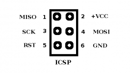
There is also set of ICSP pins on the other side, allowing direct access using serial interface.
For me - USB is more than enough (I'm not going to change the boot-loader or something like that
)Attachments
I just pop the Arduino out and connect it but I think pins D0 & D1 are com lines.
That's right
I should pull the protection circuit fuse and measure the current draw. My transformer is rated for.810ma per output. The three large relays should draw half that. There's brown stuff (transformer magic smoke equivalent) running out the bottom. I've replaced the transformer and disconnected the tube transformer relay. This one's running cooler.
- Status
- This old topic is closed. If you want to reopen this topic, contact a moderator using the "Report Post" button.
- Home
- Amplifiers
- Solid State
- How to build a 21st century protection board