Okay so I'm hoping this is the right place to post this..
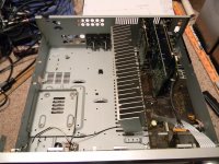
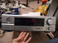
I received a Denon AVR-485 from a friend, in non-working condition. It had a power supply Issue, and I believe the amps were done for as well. I decided to try to rebuild it, as everything else worked. I managed to find the service manual for this thing, and I tell you.. I don't understand why they did some of the things they did..
After going through all the board schematics I found I needed a -33v supply for the screen, a 24v supply for the relays, and this feeds a 12v regulator. Dual 15v rails for the audio input board, and various other things. A 5.6v supply for the CPU board, and finally a 5v supply for the DSP board..
Okay so the -33v can be from Vdd to like -45 on an LC75725 (the one in this receiver is a LC75721, but couldn't find a datasheet) so I can get away with -24v. They used a zener diode/transistor supply for that in the receiver. The 5.6v rail came from a 5v regulator, with some shutdown circuitry, but we dont need that. I knew what I needed and got to work.
The 5.6v supply comes from a small aux transformer, and is powered on when the main switch on the front panel is pushed. This sends the 5.6v to the CPU board, and if there are no faults detected that sends a signal to a relay which turns on the main transformer. It then runs a self test, and turns all the relays on if it passes.
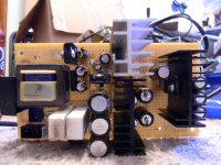
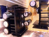
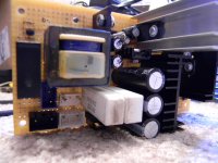
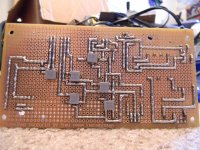
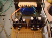
I have dual 24v rails, dual 15v rails, 5.6v rail, and a 5v rail.. all on this little board that measures 141mm long by 74mm wide by 65mm tall. The height might get reduced if cutting the heatsink down is permissible, have yet to test the thermal dissipation of that heatsink.. The 15v regulators heatsink rises about 20 degrees, so things should be okay with them being that close to the caps (which are 105 degree rated) I need better caps for the 5v supply, and need to place a few more decoupling caps yet. Oh and add the connectors, waiting for them to arrive.
So, how do you guys think I did? I personally think I went too small, and didnt pay enough attention the layout.
The next step will be to wire it up in its final spot, and start working on the preamplifier boards, and getting some amplifier modules mounted on the heatsink. Updates to come")
I received a Denon AVR-485 from a friend, in non-working condition. It had a power supply Issue, and I believe the amps were done for as well. I decided to try to rebuild it, as everything else worked. I managed to find the service manual for this thing, and I tell you.. I don't understand why they did some of the things they did..
After going through all the board schematics I found I needed a -33v supply for the screen, a 24v supply for the relays, and this feeds a 12v regulator. Dual 15v rails for the audio input board, and various other things. A 5.6v supply for the CPU board, and finally a 5v supply for the DSP board..
Okay so the -33v can be from Vdd to like -45 on an LC75725 (the one in this receiver is a LC75721, but couldn't find a datasheet) so I can get away with -24v. They used a zener diode/transistor supply for that in the receiver. The 5.6v rail came from a 5v regulator, with some shutdown circuitry, but we dont need that. I knew what I needed and got to work.
The 5.6v supply comes from a small aux transformer, and is powered on when the main switch on the front panel is pushed. This sends the 5.6v to the CPU board, and if there are no faults detected that sends a signal to a relay which turns on the main transformer. It then runs a self test, and turns all the relays on if it passes.
I have dual 24v rails, dual 15v rails, 5.6v rail, and a 5v rail.. all on this little board that measures 141mm long by 74mm wide by 65mm tall. The height might get reduced if cutting the heatsink down is permissible, have yet to test the thermal dissipation of that heatsink.. The 15v regulators heatsink rises about 20 degrees, so things should be okay with them being that close to the caps (which are 105 degree rated) I need better caps for the 5v supply, and need to place a few more decoupling caps yet. Oh and add the connectors, waiting for them to arrive.
So, how do you guys think I did? I personally think I went too small, and didnt pay enough attention the layout.
The next step will be to wire it up in its final spot, and start working on the preamplifier boards, and getting some amplifier modules mounted on the heatsink. Updates to come
Attachments
ineedaname - You're my new hero.
Seriously I thought I was the only one getting into these HT amps to try to fix them.
I have not done this deep a job - I'll be watching this thread.
You're fixing it into its original design, or building a different amp in the chassis ?
Thanks.
Srinath.
Seriously I thought I was the only one getting into these HT amps to try to fix them.
I have not done this deep a job - I'll be watching this thread.
You're fixing it into its original design, or building a different amp in the chassis ?
Thanks.
Srinath.
I want better amps in this thing, and I don't need 6 amps anyway.. That is just crazy.. I Will probably be doing something like LM3875 amps or something simple for now, until my budget allows for more (I already have a few of these amps laying around)
I have decided thought to rebuild the power supply, because I realize I should include some of the protection circuitry. I will be adding the power down circuit, and a couple things for the protection pin, nowhere near original though (they have like 5 things that can go wrong and trip it) I have ordered the parts so hopefully they will be here tomorrow, Digi-Key is usually pretty fast for me. Once I have the layout sketched up, I will post it and maybe you guys can help me find some errors. I got lucky on that first one, and it worked first time around. I will be winding my own transformer for the power supply too. (I have an old 25VA toroidal transformer laying around)
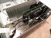
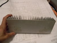
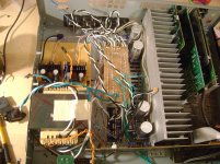
Here are some pics (the knob isn't missing, it's laying over there somewhere) Look at that heatsink, its beautiful!!! 278mm x 100mm x 46mm Guessing around .5C/W or so based on similar sized ones I found online.
Can you stack toroidal transformers, like one on top of the other?
I have decided thought to rebuild the power supply, because I realize I should include some of the protection circuitry. I will be adding the power down circuit, and a couple things for the protection pin, nowhere near original though (they have like 5 things that can go wrong and trip it) I have ordered the parts so hopefully they will be here tomorrow, Digi-Key is usually pretty fast for me. Once I have the layout sketched up, I will post it and maybe you guys can help me find some errors. I got lucky on that first one, and it worked first time around. I will be winding my own transformer for the power supply too. (I have an old 25VA toroidal transformer laying around)
Here are some pics (the knob isn't missing, it's laying over there somewhere) Look at that heatsink, its beautiful!!! 278mm x 100mm x 46mm Guessing around .5C/W or so based on similar sized ones I found online.
Can you stack toroidal transformers, like one on top of the other?
Attachments
sorry, but from my point of view is wasting time.. This amp in mint condition i can buy for 50 USD... I think there is just one useful thing - heatsink
Yes, but doesn't look like he's interested in the stock design. Since the amps are blown anyway, he's decided to use it for the base of a diy project.
Can you stack toroidal transformers, like one on top of the other?
Should be fine, make sure that they are both connected in phase with each other.
In other words make sure the same color wires on the primary are connected in parallel.
Also make sure there is a gap between the two for cooling. There are different ways you
could do this. But I would probably want to use rubber pads to space them, plus it would help dampen and any vibration between them.
heatsink and transformer
More than heatsink I think the transformer is what is worth the $$$.
I've picked up a few dead amps for 20 or less.
Cool.
Srinath.
Yes, but doesn't look like he's interested in the stock design. Since the amps are blown anyway, he's decided to use it for the base of a diy project.
More than heatsink I think the transformer is what is worth the $$$.
I've picked up a few dead amps for 20 or less.
Cool.
Srinath.
Yeah the main reason I am rebuilding this is because it already has the input selector, volume control, preamps, subwoofer output, etc, etc. Plus it was free, and only needs a power supply, which I spent like 30 bucks on parts for (went a little above and beyond with quality parts) So every dollar I put into this from now on will be on amplifier modules, and the power supplies for them. Basically just something for fun to tinker around with. I will maybe even shoot a few videos going over basic things to help people debug this thing.
Okay so I got bored with having just my amps lay out on my desk and using my laptop to run everything.. I finished up the power supply, and threw together this disaster of a setup. It is currently working, although obviously if you can't already guess, it is far from quiet. I took apart an old Pioneer transformer and rewound it for the voltages I needed, an JB Wlded the "I" back on.. Not pretty but it is functional.
Attachments
- Status
- This old topic is closed. If you want to reopen this topic, contact a moderator using the "Report Post" button.
- Home
- Amplifiers
- Solid State
- Denon AVR-485 Repair