Hello,
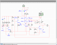
I've tried to simulate the loudspeaker protection circuit from this website (www.diyaudio.com/media/build-guides/diyaudio-speakerprotector-build-guide-v1.0.pdf+&cd=5&hl=de&ct=clnk&gl=de) and it doesnt work. I tried everything and I hope that someone could help me.
I've tried to simulate the loudspeaker protection circuit from this website (www.diyaudio.com/media/build-guides/diyaudio-speakerprotector-build-guide-v1.0.pdf+&cd=5&hl=de&ct=clnk&gl=de) and it doesnt work. I tried everything and I hope that someone could help me.
Attachments
But there's the next problem:
The circuit doesn't switch on the speakers until the frequency of the input signal isn't less than 100hz. I'm a beginner in this sector, so I have no idea what could be wrong. Could someone help me with this problem?
(@alex mm: You probably have written the description of my error in the wrong sector of the picture, because where you have written it, there is the input of the (music) signal that I tried to simulate whit an AC signal. And the input signal have to be sinusoidal. I think that you mean the source voltage.)
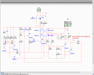
......wrong it's your approach unfortunately , you do not understand how it's functioning this protection board . Only if you have +/- DC voltage on output amplifier will release the relay ...... This protection board will not work with sinusoidal signal ,it's not an audio amplifier . I wrote correctly in right place on schematic and proper words . This board it's working properly and was sell as an commercial product .
The relays will turn on a few milliseconds after you turn the amp on, when Q3 base reaches +7.5V .
The time delay comes from C3 charging through Rs .
Voltage to feed all this comes from rectified AC ,from some power transformer winding, which I hope you tried to simulate with generator XFG1 ... although you failed to define its voltage and frequency and it looks like you set it to squarewave .
BIG problem with simulators is although they are powerful tools, they also can give you a false sense of security if you just throw circuits at them but don't really know how they work.
First you need to understand how stuff works, then use the simulator to test various "what if" situations without actually having to build all of them physically.
And after you are happy with one, build it in the real world to see what happens.
Just 2 days ago somebody was very worried about his power supply diodes, because simulation showed they passed 41 A peaks ... while actual measurement (wise guy he actually built and tested the supply) showed 4A peaks.
Was the simulator wrong?
Well, not mathematically, of course, but nobody told it that the voltage generator feeding it did not have zero ohms internal impedance ... far from a real world transformer.
So besides using the simulator, also "do your homework".
Which in this case is: imagine what's needed to turn relays on or off and analyze the circuit for how and when that is achieved.
Last edited:
Thank's to Alex mm and sregor. Now I understand.
Now it`s working exept the switch on relay. I tried to Change capacits and resists but nothing, the relays turn on immediatly, when I start the simulation
As JMFahey explained, this is what it is supposed to do. Try adding DC to the input (+ or -) and eventually it should shut off...
- Status
- This old topic is closed. If you want to reopen this topic, contact a moderator using the "Report Post" button.
- Home
- Amplifiers
- Solid State
- Loudspeaker protection circuit (form diyaudio) problem