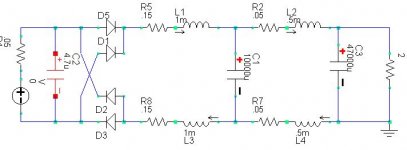
In power supply there are some people are using Pi Filter (L-C) filter for ripple elimination. The L is usually placed on +rail and -rail, while the Capacitors are to ground.
I looked in some commercial amps, they use the common windings for this L. That is the +rail and -rail chokes are wound on the same core.
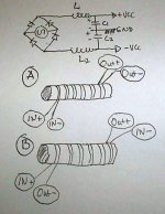
A question rises in my mind, wheter it is the A input-output configuration, or the B configuration is the right one.
The winding have the same direction for the 2 magnet wire. In A, both + and - input are in the same place, so I think the magnetic field will eliminate with each other.
But in B configuration, the input and output of + and - are crossing. So the magnetic field will add to each other.
Which is the right input-output configuration that is the right one for Pi filter after bridging diode?
I looked in some commercial amps, they use the common windings for this L. That is the +rail and -rail chokes are wound on the same core.
A question rises in my mind, wheter it is the A input-output configuration, or the B configuration is the right one.
The winding have the same direction for the 2 magnet wire. In A, both + and - input are in the same place, so I think the magnetic field will eliminate with each other.
But in B configuration, the input and output of + and - are crossing. So the magnetic field will add to each other.
Which is the right input-output configuration that is the right one for Pi filter after bridging diode?
Attachments
you need a dual secondary transformer with the two windings in series for a dual supply. the centre point of the two windings defines the earth in between the two rails. You cannot rely on caps alone to define the earth between the rails - it will not work
also you need a cap in between the bridge and the choke.
that is: transformer, bridge, C, L, C
A classic Pi filter has a single choke in in a single rail supply usually drawn at the top hence the name.
good luck
also you need a cap in between the bridge and the choke.
that is: transformer, bridge, C, L, C
A classic Pi filter has a single choke in in a single rail supply usually drawn at the top hence the name.
good luck
Yes, you are right. I forgot to draw the transformer, but it is certainly the CT (Center Tap) type, so ground is taken from this CT, not only from the junction of capacitors.
From the commercial unit I observed, it seems like it used B configuration, but I'm not sure, because it was hard to see it.
Which configuration is the right one?
From the commercial unit I observed, it seems like it used B configuration, but I'm not sure, because it was hard to see it.
Which configuration is the right one?
Lumanauw,
B is the right one if you want to use the L's for smoothing out the current pulse of the rectifier and improve the power factor. This is a very desirable thing, as you can get more power from the same transformer and the amount of conducted and radiated interference is seriously decreased. Also the rectifiers are less stressed.
Because you want to store magnetic field-energy in the core you want the fields to add and not cancel. Otherwise no energy is stored and you just get an common mode rejection coil and you are not interested in a common mode disturbance in this case but in the differential signal (the output power).
Steven
You need two seperate chokes for this to work properly,I think what you have seen is a common mode choke . Idealy a choke input supply (i.e. TX to rectifier then choke to smoothing caps) could be used to give almost constant current draw from the transformer but this is nomally only done on supplys for valve amps because of the size of choke that would be necessary for a solid state power amp (huge and two of them!).Musical fidelity (British fidelity in the states I believe) used this however in the A470 power amp but it took two people to lift one.
I suppose these coils are not used as common mode choke, to suppress common mode interferences, but really as input chokes to stretch the active charging current pulse through the rectifier to charge the capacitors. This used to be done in the past mainly for tube amplifiers because tube rectifiers could not handle big current peaks and it helped in smoothing DC with the relatively small value electrolytic caps. These chokes were even used to stabilize the output voltage under changing load conditions. This was done with a so-called swinging choke. At small DC currents the inductance was high, causing some voltage drop, at higher currents the core came slowly into saturation and the inductance dropped, causing a smaller voltage drop. When Si-diodes, able to handle large current peaks, appeared, the input choke lost some of its value. Interestingly, the swinging choke re-appears in switched mode power supplies as stepped choke with high inductance at low currents an low inductance at high currents. This is done via a stepped airgap. By using this it is possible to increase the efficiency of switched mode power supplies at low currrent demands, like in the stand by mode of TVs and VCRs.
For some decades this choke approach was hardly used because of high cost and the availability of cheap high current diodes and high value electrolytics. About 5 years ago the input choke gained interest again, also for low voltage equipment, because of the European and Japanese mains harmonic requirements (IEC 61000-3-2). This standard asks for low harmonic distortion of the current wave form as it is drawn from the mains and sets limits to the values of all harmonics up to the 39th. The simple bridge rectifier with capacitor does not fulfil these limits and manufacturers have started to use input coils again to to be compliant. This is in fact a passive power factor correction circuit. Just like switched mode power supplies use active power factor correction circuits to be compliant. A few years ago the introduction of the standard was postponed, however, for most commercial equipment, because of objections from the manufacturers/market due to increased costs.
In the past most of the (tube) equipment used and still use single power supplies that need only one choke, while most modern solid state amplifiers use double power supplies. Double power supplies need two chokes but, I think, there is no reason why these chokes could not be on the same core, if you make sure that the magnetic fields are added and not cancelled. Of course the core needs to be bigger for two windings to give them both the same inductance as each would have had when wound on a separate core. In Lumanauw's circuit double phase rectification is used in both supply lines so the fields allways add up (if the proper winding direction is used) and the core should not saturate because of that. In single phase rectification it is possible to drive one coil during half a mains period and the other coil during the other half, in which case the maximum density would not increase, but with the disadvantage of more ripple.
So, I think, it makes no real difference whether you use two smaller cores for each supply or one bigger for both supplies at the same time. In commercial equipment the designer often prefers to use one component instead of two, because that is cheaper.
Steven
thanks Steven for that explaination, I had not seen chokes in this position before and I will definetly do some research on it.
I have found that 1uF - 4.7uF cap directly across the secondary has a hugely beneficial effect on the sound quality of every PSU that I have tried it on.
Although in theory it is less elegant that a carefully designed snubber cct it seems to do 90% of the job by drastically reducing the frequency of the resonance in the coils after the diodes switch off.
I will now do some spice research into how to these two elements can be combined to best effects.
have you ever tried caps directly across secondaries ?
I just played around with these ideas in spice.
This is what I found
One 4.7uF cap across secondary still gives ringing but much much lower frequency.
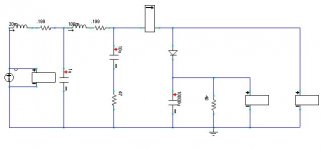
1uF in paralell with 10uF + 47 ohms ( see picture below ) reduces frequency and nearly kills the ringing. The general rule of thumb is that the single cap has to 1/10 of the value of the cap in series with the resistor for effective damping. Damping can be optimised to reduce ringing to about 1 cycle or less by adjusting resistor value.
Adding in a 100mH choke certainly can extend the pulse duration to about twice the time (8ms to about 16ms ) but be prepaired for big loss of voltage at the o/p. In the cct below the o/p voltage was almost halved. Choke values that did not reduce the voltage much did not significantly increase the pulse time.
Using the choke without the caps does nothing to address the high frequency ringing when the diodes turn off so there still may be a rough quality to equiptment using such a supply.
In the high voltage valve equiptment the choke would have to be a higher value and therefore would naturally have a higher resistance and this would have a damping affect on the ringing.
I'm a big fan of simple RLC type passive designs so next time I am doing a suitable supply I will try this choke idea.
cheers
mike
This is what I found
One 4.7uF cap across secondary still gives ringing but much much lower frequency.
1uF in paralell with 10uF + 47 ohms ( see picture below ) reduces frequency and nearly kills the ringing. The general rule of thumb is that the single cap has to 1/10 of the value of the cap in series with the resistor for effective damping. Damping can be optimised to reduce ringing to about 1 cycle or less by adjusting resistor value.
Adding in a 100mH choke certainly can extend the pulse duration to about twice the time (8ms to about 16ms ) but be prepaired for big loss of voltage at the o/p. In the cct below the o/p voltage was almost halved. Choke values that did not reduce the voltage much did not significantly increase the pulse time.
Using the choke without the caps does nothing to address the high frequency ringing when the diodes turn off so there still may be a rough quality to equiptment using such a supply.
In the high voltage valve equiptment the choke would have to be a higher value and therefore would naturally have a higher resistance and this would have a damping affect on the ringing.
I'm a big fan of simple RLC type passive designs so next time I am doing a suitable supply I will try this choke idea.
cheers
mike
Attachments

well my spice runs at a snails pace whem trying to look at a choke in between the diode and smoothing cap.
So far it is clear that lenght of the current pulse is proportional to the current so this idea seems to be restricted to fairly constant current cct's.
Does that seem logical ?
i'll leave the spice cct running overnight !
having looked at your web site lumanauw, I wonder if this idea was meant for a valve amp. If so it might be posted in the wrong place
mike
mikelm,
You're right in noticing that the output voltage will drop by inserting a choke before the first supply capacitor, i.e. by using an input choke. In fact, if the value of the choke is above the critical value (approx L=Vdc/1000Idc for 60Hz with double phase rectification and 20% more for 50Hz mains, e.g. 30mH for 50Vdc, 2Adc and 50Hz mains) the current through the rectifiers will never switch off. The output voltage is not determined by the peak value of Vac anymore (1.41Vac), but by the average to rms ratio of the double phase rectified sine wave, which is 0.9: Vdc=0.9Vac, which is significantly lower than the peak value of Vac. But this voltage drop is not a loss in efficiency, only a lower output voltage, and less current is drawn from the transformer. This should be compensated for by choosing a higher secondary transformer voltage. Note that the critical inductance is determined by the DC current, so a minimum current is required to keep the rectifier bridge conducting the full cycle. This could very well be a class A amplifier. For a larger current the output voltage will stay at 0.9Vac. Often a lower value than the critical value will be used, and then the the conducting period of the rectifier will be stretched but the rectifier will still switch. The output voltage will be between 1.41Vac and 0.9Vac. With some bad luck you have taken a value for the choke that gives a widely varying output voltage if a class AB amplifier goes from no load to full load. Then it is better to take a smaller choke value or use a swinging choke of which the inductance goes up when the current goes down.
By adding a (small) capacitor before the choke the ouput voltage will increase again, because that one will be charged again to 1.41Vac. This capacitor can be smaller than the one after the choke, so still rectifier current peaks are less severe than if all the capacitance would have been connected directly after the bridge.
Steven
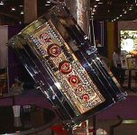
Ya, that explain why this common mode chokes always bigger than the transformer itself.
This picture is an audio power amp, but with switching power supplies. The bigger core windings are not transformer, they are this common mode chokes. The smaller toroids are the smps transformer.
This picture is an audio power amp, but with switching power supplies. The bigger core windings are not transformer, they are this common mode chokes. The smaller toroids are the smps transformer.
Attachments
Many thanks Lumanauw for the idea, and Steven for the comrehensive explanation.
I am currently using normal CLC regulation on my class A amps so I am quite familiar with this.
However I have now designed as spice tested the supply below for a another class A amp which I am working on now ( and will present once I have it working in real life )
This seems brilliant,...a truly Class A PSU, no switching. I am looking forword to hearing the smooth sound this should produce.
Steven and all
could you have a look at this and see what you think.
what do you think about choice of core material ?
Air would be to big and with 6A DC flowing a transformer core with no gap would be heavily saturated. would this really matter ? or...
would iron dust cores be the way to go ?
thanks
mike
Attachments
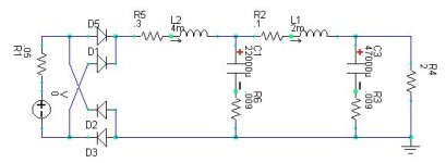
This version shows a similar effect only with coupled inductors in both legs which refers back to the original question
I wonder, are mutual inductors like this necessary for a single rail supply ? or could I just earth the neg rail ?
( the resistors next to the caps on the previous cct were only there to help spice run when the cct was ringing. )
I wonder, are mutual inductors like this necessary for a single rail supply ? or could I just earth the neg rail ?
( the resistors next to the caps on the previous cct were only there to help spice run when the cct was ringing. )
Attachments
mikelm said:
This seems brilliant,...a truly Class A PSU, no switching. I am looking forword to hearing the smooth sound this should produce.
Steven and all, could you have a look at this and see what you think.
What do you think about choice of core material ?
Air would be to big and with 6A DC flowing a transformer core with no gap would be heavily saturated. would this really matter ? or... would iron dust cores be the way to go?
Hi mikelm,
Yep, I had this in mind for some time and even thought in the same way as you: it's a sort of Class A rectifier. I only did no simulations on it yet, nor did I build it. Something on my to do-list.
The choke will be quite heavy though and I would not be surprised if it turns out to be almost of the same size as the mains transformer. But for a diy audio fanatic that should not be a problem. Also the efficiency of the mains transformer improves dramaticaly and you can use a smaller one for the same output power and the same temperature rise of the transformer. This is because the current demand is more sinusoid now instead of drawn in narrow current peaks. The copper losses will be less.
An air core would be very big indeed, and a choke wound on a tranformer core with no gap would easily saturate, causing the inductance to drop. In fact a kind of swinging choke would be obtained in such a way. I think for a Class A power amplifier with a steady current demand, I would go for a normal (non swinging) choke. A core with a gap will probably give even more inductance than the saturating no-gap core in the same volume at the same DC current. But that's a guess.
I would use an E/I core with a suitable air gap for the chosen DC current. I'm not sure but maybe these big coils for loudspeaker crossovers with air gaps can be used. See Mundorf
Steven
Hi, Everyone,
I'm not quite inside this class A psu yet. Is it because the L is big enough (above the critical value, acc to Steven), so the rectifiers are conduct all the time, so it is called class A psu?
Also, I found many cases of manufacturer who put C before L (after bridge rectifier) and then another C after the L.
While some other manufacture connect bridge diode direct to L, not having any C between, and C is put after L.
What is the purpose and difference between these two?
- Status
- This old topic is closed. If you want to reopen this topic, contact a moderator using the "Report Post" button.
- Home
- Amplifiers
- Solid State
- Choke for Pi Filter