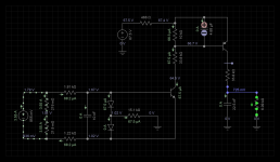
the spk-in passes through 120k and is filtered with 330uF to then feed pin2.
The 91k increases the time constant.
The R6+C3 time constant is ~40seconds to reach ~60% of the input signal.
Adding R7 probably increases RC to over a minute.
That seems far too slow.
One second would be more appropriate.
Try reducing C3 to 3u3F MKT and temporarily remove R7. Change R6 to suit the final RC value you require.
If voltage limiting is required for pin2, then add a protecting Zener across C3.
This is DC protection that you commented on. Does your comment imply that the DC trigger time will be as low as 1 minute using the values in my design?
I calculated R6 and R7 using the formulas in the data sheet to get DC protection triggered with anything outside +2V to -2V threshold. For C3 I used the same value as in the data sheet reference design.
For comparison here are the R6, R7 and C3 values in the amplifiers that I found use the same/similar IC:
Sony TA N1 (uses uPC1237):
R6: 330k
R7: 220k
C3: 220uF
Marantz PM 55 (uses TA7317P):
R6: 68k
R7: absent
C3: 47uF
Technics SE H100 (uses TA7317P)
R8: 180k
R7: 22k
C3: 100uF
uPC1237 data sheet example suggests these values (based on DC threshold +1.24V to -1.04V):
R6: 56k
R7: absent
C3: 330uF'
Generally over-current protection gives me more headache than DC protection since things are less clear there and it is more difficult to test how it should be properly connected.
Last edited:
test your DC detect and trigger using a 9V battery and see how quickly it triggers.
Then try a 1.5V battery and see if it triggers and how long it takes. You might want to try other DC test/fault voltages from 3Vdc to 40Vdc and from -1.5Vdc to -40Vdc.
Then input a high level medium frequency signal and check it does not trigger. Slowly reduce the frequency. Eventually it will trigger. Maybe at 20Hz or 10Hz or 5Hz. Find out what frequency and level it triggers at. Are you happy with that?
If it triggers at too high a frequency, then increase the RC, or add in R7, but you must re-check the DC triggering levels and speeds.
Last edited:
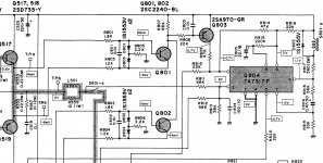
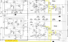
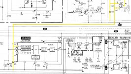
Found one more example of over-current protection using the IC, the power amp is Toshiba SC 530.
Toshiba uses both halves of the output signal to trigger the protection. This is the first time I see it done in a production amplifier.
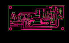
I updated my own schematics to do the same. BRD1 and BRD2 go to the emitters of output transistors
Toshiba uses both halves of the output signal to trigger the protection. This is the first time I see it done in a production amplifier.
I updated my own schematics to do the same. BRD1 and BRD2 go to the emitters of output transistors
Attachments
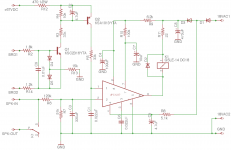
I ran my overcurrent protection through circuit simulator. With the selected R and C values in the schematic (and default transistor selection - I couldn't find how to customize transistors in the emulator) uPC1237 triggers when the current through a pair of amplifier output stage transistors reaches around 3.55A
I am using 3 pairs of NJW0281G (NPN) NJW0302G (PNP) in the output stage (this is Honey Badger). These are rated to 15A collector / emitter continuous current. It 3.55A too aggressive?
How does collector / emitter current translate to the current through the speaker? Do I just multiply it by the number of transistor pairs (3 in my case)?
Note to myself: I can tune up the current threshold by varying R4 value. R4 of 2.2K gives threshold of 6.7A and 1K gives 11A
Attachments
Last edited:
you should be looking at continuous DC current and longer term AC current and short term AC transient peak currents.I ran my overcurrent protection through circuit simulator. With the selected R and C values in the schematic (and default transistor selection - I couldn't find how to customize transistors in the emulator) uPC1237 triggers when the current through a pair of amplifier output stage transistors reaches around 3.55A
I am using 3 pairs of NJW0281G (NPN) NJW0302G (PNP) in the output stage (this is Honey Badger). These are rated to 15A collector / emitter continuous current. It 3.55A too aggressive?
How does collector / emitter current translate to the current through the speaker? Do I just multiply it by the number of transistor pairs (3 in my case)?
Note to myself: I can tune up the current threshold by varying R4 value. R4 of 2.2K gives threshold of 6.7A and 1K gives 11A
All three conditions and all those across the whole spectrum need to be detected and appropriate action (or non-action) taken to protect your speakers.
Look at the datasheet and extract the DC, long term and short term SOA limits for your chosen Vce.
Then arrange for the detector to read and apply triggering.
I'll repeat my interpretation of a good IV limiter:
All valid audio signals should pass to all valid audio loads.
Last edited:
I assembled and connected the board as per schematic in post #84. It detects shorted speaker and DC - I tested these scenarios on the assembled board. I didn't test high current scenario.
Something happened last night thought that made me question if my protection works. I connected 220Hz sine input and cranked the volume up to max with no speakers connected. I had a scope on the left channel which registered peak 65V output. At this point one of the 4A power fuses blew. The protection didn't detect anything.
Is it correct to assume that my R4 value is probably too low and I should increase the sensitivity of the overcurrent protection circuit? Or is it just the unusual way I did the experiment that caused the protection to fail to see anything and it would do so OK if a normal speaker was connected?
Hi reedcat,
Your question hasn't been addressed yet.
You have 3 output transistors of each type in your output stage. So your trip current will be approximately 3 x 3.55 amperes, or 10.65 amperes. That is a more than reasonable trip point I would think.
So why don't we use an output transistor to it's full rated current and temperature dissipation? If you take a look at the datasheet for your output transistors, look for something called an SOA curve. Keep in mind that these are for resistive loads, no phase angle between the voltage and current components. You can see that as the voltage is increased across a transistor, the second breakdown limit restricts the current through the transistor. Now when you are powering a set of real speakers, they are what is called a reactive load. Depending on the frequency, there will be a capacitive component or inductive component to the load the amplifier sees. These reactive components change the phase angle from 0° to some other value. What this actually means to you is that the peak current flow does not occur at the peak voltage across the speakers. That means that at the zero crossing, your current is not zero and the transistors will be conducting current in a worst case situation. That means that you look at the full supply voltage on the SOA graph and determine what the safe maximum current the transistor can pass under those conditions. It's a lot less than the 15 ampere rating, isn't it? That's at 25 °C, once you heat things up, that current will be even less.
So that is why transistors cannot be used to their full rated values. Your protection circuit should be set up to limit current in the output stage to safe values, taking into account the tolerance of the emitter resistors where you sample the voltage drop.
You should be glad you weren't working in the 70's when transistors weren't nearly as good as they are today!
-Chris
Thank you, Chris. I got myself The Art of Electronics by Horowitz Hill and as i read it these explanations make more and more sense!
Here is the reason I asked if this is too aggressive. 10.65 amperes is all good for 8 Ohm load but it corresponds to only 170 Watt of peak power over 4 Ohm. From reading the build thread (Honey Badger) I recall that the amplifier is able to handle 250 Watt with 4 Ohm speakers (15.6 amperes), and output transistors can handle it (each picks up a third of that).
So, my concern is that the protection will trigger prematurely when I connect it to 4 Ohm. I have not tried it yet with 4 Ohm, I don't have the speakers. But at some point I will and this will be an annoyance. :-(
Hi reedcat,
You have to ask yourself a serious question. Do you really want to dump 250 watts into any speaker? Most of the energy is turned into heat. Let's call your speaker 5% efficient. It's probably less, so this is an optimistic exercise.
The heat energy in a speaker is dissipated by the voice coil / former / magnet structure. It isn't a path with low resistance by any means, most of the heat is locked into the voice coil. Look at a voice coil, call it 3" across. Now figure out how hot a coil of wire is going to be if you pump about 16 watts continuously into it. 250 W * .95 / 15 = 15.83 watts assuming a 15 to 1 peak to rms ratio. Doesn't sound like much, but if you connect a DC power supply to a 3" voice coil and dissipate 16 watts into it for a while, you will see the voice coil either unglue itself, or burn. Certainly the former will warp. That woofer will be done. If you run music that is more compressed, the ratio will come back from 15:1 down to 10:1 or even lower. Once you get into clipping, that voice coil will be slapping into the back plate in the speaker and be mashed over, causing a rubbing or seized voice coil. It may well be striking the back plate by the time you hit 150 watts peak. Depends on the speaker.
So, do you really want to allow 10.65 amperes to flow into a speaker system? Keep in mind that a fuse averages the power because it is a thermal device, so your current will likely approximate 15 amps for a continuous since wave and for music with a peak to steady power ratio of 15:1, you're looking at 225 amperes instantaneously. Your power supply may not be able to support that power level. I haven't even mentioned what will happen to the crossover stuck in the middle. Kiss that goodbye too. I have seen this situation many times, especially when Carver M-1.5t or M-4.0t amplifiers are in service. A common comment was that the music was clean and not clipping and the bass got distorted and stopped before anyone could react.
My Marantz 300DC can bottom the PSB Stratus Gold speakers without clipping. It's rated at 150 wpc. The speakers are rated at 4 ohm. I have a friend that used to do this until I explained what was happening. Those voice coils are damaged already, nothing I can do about that.
-Chris

- Home
- Amplifiers
- Solid State
- Overload detection circuit for UPC1237