I want use this amplifier for 4ohm so yes multiple pairs
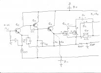
Here is my fast & provisional schematic with inserted follower (Q3) which allow to drive multiple output power LatFets , only half of the Amp is showed , but you have to find where lower side of follower emitter res. ( Re) is best rail point to connect , on the speaker rail , on the B- rail ,or even on the ground rail .
( BTW I like that generic simple VSSA Circlotron design with only two output power N type LatFets .since I deal with 16ohm (load)speaker )
Attachments
Hi UltimateX86,
I can't run your simulation right now but I think it will work in principle. I'd suggest checking all DC operating points with no signal to be sure they're where they belong.
Also, V2-V3 can be 24V or less, and the PNPs can be small signal devices idling at 5-10 mA. These changes are optional but may reduce build cost somewhat.
with 24V or less, ssm2210 / ssm2220 could be used ?
Last edited:
Thank you banat, i'll run a sim.
You are Welcome !
BTW ,
having separate B+/B- supply rails for this type of fully balanced CFA amp is on the first sight disadvantage ( more complicated PSU ) ,but in the same time is Big advantage since B+/B- rails can be in the real Amp well regulated & clean and in the same time with value way above B1/B2 OPS - PSU , which can directly allow to design input/driver stages with very clean and undistorted drive signals for OPS LatFets gates .
I found this one for the VAS : http://jm.plantefeve.pagesperso-orange.fr/10WMT.gif
I found this one for the VAS : http://jm.plantefeve.pagesperso-orange.fr/10WMT.gif
For shure that it is possible to acomodate that VAS on your VSSA Circlotron project , it is look nice with that CCS on VAS collector side , any way try to simulate this schematic to .
Attachments
Joe, so this will made a differential pair ?
In this instance it's probably more correct to say that it (the resistor described in post #5) completes a differential feedback loop around the amplifier. Overall differential behavior is enhanced, but if you drive the amp from a single-ended signal source (one side grounded), I think you will still see some asymmetry.
Well, I may have to take back what I said above about asymmetry. I just simmed a version of your circuit with differential feedback and it worked pretty darn well even with a single-ended input...
Can you post your schematic?
Thanks
Do
Thanks, it is quite appealing...
I have found the Fet Circlotron documentation from Michael Rothacher and I wonder if you have tried it...
Fab
Can you post your schematic?
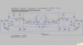
It's basically the circuit UltimateX86 first presented, but with differential feedback applied as described in post #5. There is one other difference, which is that the output stage uses two HEXFETs biased as shown in the Thorens TEM3200 conceptual schematic that you see out on the web.
I first saw this bias arrangement in a BJT circlotron design that appeared in No.8 1984 of RadioHobby, a Russian magazine. It was essentially a lower-power version of the Sumo Nine, with the important difference that the bias current is regulated by a constant current source rather than resistors. This allows for the possibility of temperature compensation, and with that, for the use of either BJTs or high-gm MOSFETs as output devices.
However, this arrangement is not so good for use with lateral MOSFETs in the output, because it limits their drive voltage to twice the bias voltage, which is not nearly enough for full output current. It would probably work well with power JFETs, though.
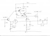
A Frensh forumer proposion to drive mosfet :
http://img11.hostingpics.net/pics/240637updateustage.png
http://img11.hostingpics.net/pics/240637updateustage.png
A Frensh forumer proposion to drive mosfet :
http://img11.hostingpics.net/pics/240637updateustage.png
Thanks. I suppose that it is the 560 ohms resistor that represents the pot.... Is the additional transistor (Q3) used to share the power with follower transistor?
Fab
Last edited:
I think some followers is must but just in case if you want to drive multiple pairs of power output LatFets .
On item 2 of 6moons audioreviews: Thorens TEM 3200 - Sidebar III it suggests a single very high power MOSFET. Any idea which one would suit this purpose while being good for audio...?
Fab
On item 2 of 6moons audioreviews: Thorens TEM*3200 - Sidebar III it suggests a single very high power MOSFET. Any idea which one would suit this purpose while being good for audio...?
Fab
Hi Fab !
As I remember Thorens TEM 3200 Circlotron Amp. is DC coupled hybrid one , which power Fet`s Thorens use honestly I don`t know , but it is obvious that is some very powerful devices used there.
Any way , personally to have any chance I will use some power SIT `s for this from UltimateX 86 excellent designed Circlotron CFB Amp .
") , but for now some K1058 ( K135 ) will be just OK for me .
, but for now some K1058 ( K135 ) will be just OK for me . I think that is important to say that this balanced bridge configuration allow almost Perfect matching between active devices of the left side and the mirrored right side of this balanced amp , which can finaly results in many positive Amp performance , low to almost non existent output DC off set , low THD , thanks to CFB in very high slew rate characteristic , .........
Best Regards !
Last edited:
In this instance it's probably more correct to say that it (the resistor described in post #5) completes a differential feedback loop around the amplifier. Overall differential behavior is enhanced, but if you drive the amp from a single-ended signal source (one side grounded), I think you will still see some asymmetry.
HI Joe
I have LL1690 for the input
- Status
- This old topic is closed. If you want to reopen this topic, contact a moderator using the "Report Post" button.
- Home
- Amplifiers
- Solid State
- VSSA Circlotron