I have 4 sets of MJ15003/MJ15004 on my junk box. I want to build an amplifier using them. I choose VAS LTP like symasym because it give slow slew rate  and this is my first build on amp with such topology.
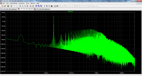
THD profile is interesting, may be it suite for subwoofer amp.
Please give suggestion how to improve this amp.
and this is my first build on amp with such topology. THD profile is interesting, may be it suite for subwoofer amp.
Please give suggestion how to improve this amp.
Attachments
I can not open the attached file
This is simulation file. Please open with LTspiceIV which is free software.
You don't say what your intended use for this design is but its certainly powerful enough for any domestic needs, at 180W.
Your total supply voltage though, is right on the power transistor Vceo ratings of 140V. Given only mild derating, the SOA
there will only allow some 0.3A current per pair at this voltage. Perhaps more realistic rail voltages of 60V would be better
to begin simulating for a real-world amplifier that can survive power variations, overloading, high temperatures etc.
You don't say what your intended use for this design is but its certainly powerful enough for any domestic needs, at 180W.
Your total supply voltage though, is right on the power transistor Vceo ratings of 140V. Given only mild derating, the SOA
there will only allow some 0.3A current per pair at this voltage. Perhaps more realistic rail voltages of 60V would be better
to begin simulating for a real-world amplifier that can survive power variations, overloading, high temperatures etc.
I only want to use my old transistor, and don't know what for
OK, I will simulate with +-63V power supply.
+-70Vdc after the supply rails have sagged to the full power level will require a 45Vac, or maybe a 50Vac transformer.
50Vac is too high for 140Vce0 devices.
45Vac may be too high, when all is at worst case conditions.
I'd suggest a 40Vac, or maybe slightly higher as your transformer.
And check/measure what voltage you get at your supply rails for worst case conditions.
40Vac will give ~ +-57Vdc to +-61Vdc depending on mains supply and quiescent current etc.
The 4pr output stage is good for 330W to 400W, all day on an appropriate heatsink.
This will easily drive a pair of 8ohms in parallel, or a 4ohms , or even a 3ohms or a pair of 6ohms.
Change the pre-drivers back to the 1406/7, or something similar.
The 12 output transistors will dissipate ~55W on +-60Vdc supplies. Provide an adequate heatsink to allow for temperature rise when you work the amplifier hard. Can one ever work a 400W amplifier hard?
The input DC blocking cap and the NFB DC blocking cap are at an extreme ratio.
If you want/need very extended bass make the input cap bigger, double, or quadruple the value.
Or for less bass extension, reduce the NFB cap by half, or even to a quarter.
Or split the difference and use 4u7F and 220uF.
Last edited:
Change the pre-drivers back to the 1406/7, or something similar.
The MJ15003/4 has 2 MHz fT. Is it necessary to use pre-driver with high fT like 1406/7? The sim result did not show the different (THD and slew rate).
The simulation file and the models that I use.
Bimo, I simulated your amp and I think that is quite good as it is. I am not familiar with this push-pull VAS, not mach help from me there.
D. Self does not like that VAS, but if you don't want EF-VAS (simpler that this one) than you can improve a bit the compensation.
increase C20 to 4p7
decrease c15 to 10p
increase resistors R34,35 to 68R (increase GM a bit)
and to lower distortion at low frequencies increase C11 to 1000u or 2200u it could be of low voltage so not big.
Damir
Hi Bimo, what do you think about cascoding the VAS like APEX SR200 ?
Cascoding make THD lower but reduce maximum peak voltage.
I checked the APEX SR200, I want to simulate it and then compare with mine.
Bimo, I simulated your amp and I think that is quite good as it is. I am not familiar with this push-pull VAS, not mach help from me there.
D. Self does not like that VAS, but if you don't want EF-VAS (simpler that this one) than you can improve a bit the compensation.
increase C20 to 4p7
decrease c15 to 10p
increase resistors R34,35 to 68R (increase GM a bit)
and to lower distortion at low frequencies increase C11 to 1000u or 2200u it could be of low voltage so not big.
Damir
Thank you very much, Damir.
I know Mr. Self only like Blameless topology
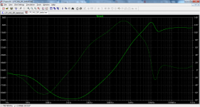
and I have designed amp with Blameless topology. It is easy to achieve low THD with decent slew rate.I sim what Damir's suggestion, it increase the slew rate from 38V/uS to 66V/uS
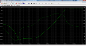
Then I change the final transistors with high fT (2SC5200 and 2SA1943). It only redure THD at 20kHz around 4x. I think, this amp not good for high frequency and the final transistors can use ancient transistor
Then I change the final transistors with high fT (2SC5200 and 2SA1943). It only redure THD at 20kHz around 4x. I think, this amp not good for high frequency and the final transistors can use ancient transistor
- Status
- This old topic is closed. If you want to reopen this topic, contact a moderator using the "Report Post" button.
- Home
- Amplifiers
- Solid State
- Amplifier for MJ15003 and MJ15004