Hello guys,
I recently finished this preamp taken by TNT TNT PreAmble - DIY solid state stereo preamplifier [English] .... I have a strange problem; start on the preamp connect the source, I rotate the volume pot and does not leave any signal / sound, only after a few minutes (even 3-5 minutes) starts to come out of the sound at a low level and distorted as time passes and the minutes sound comes out regularly and everything works fine ... weird ... Maybe it's a power supply problem? what can I check ??
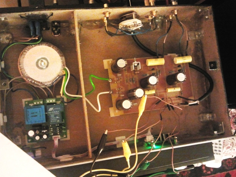
I recently finished this preamp taken by TNT TNT PreAmble - DIY solid state stereo preamplifier [English] .... I have a strange problem; start on the preamp connect the source, I rotate the volume pot and does not leave any signal / sound, only after a few minutes (even 3-5 minutes) starts to come out of the sound at a low level and distorted as time passes and the minutes sound comes out regularly and everything works fine ... weird ... Maybe it's a power supply problem? what can I check ??
Hello guys,
I recently finished this preamp taken by TNT TNT PreAmble - DIY solid state stereo preamplifier [English] .... I have a strange problem; start on the preamp connect the source, I rotate the volume pot and does not leave any signal / sound, only after a few minutes (even 3-5 minutes) starts to come out of the sound at a low level and distorted as time passes and the minutes sound comes out regularly and everything works fine ... weird ... Maybe it's a power supply problem? what can I check ??
Hi, if you use the power supply as described at the original article, than - I quote from there:
"The time constant of the network at the gate of the MOSFET is in fact higher than 2000sec... that is, the units takes something like 3 hours to reach 95% of the final voltage!!!
...
There is at least one drawback: that is, the unit is best never to be switched off, but must remain on all the time. Given the reduced power consumption, it is not a problem."
So this sort of behavior is normal by design
Switch-on today, start using tomorrow type of an amplifier

Very impractical overkill. Especially taking in account not the best performance of the circuit itself - too much distortion in my opinion.
Cheers,
Valery
Hi, if you use the power supply as described at the original article, than - I quote from there:
"The time constant of the network at the gate of the MOSFET is in fact higher than 2000sec... that is, the units takes something like 3 hours to reach 95% of the final voltage!!!
...
There is at least one drawback: that is, the unit is best never to be switched off, but must remain on all the time. Given the reduced power consumption, it is not a problem."
So this sort of behavior is normal by design
Switch-on today, start using tomorrow type of an amplifier
Very impractical overkill. Especially taking in account not the best performance of the circuit itself - too much distortion in my opinion.
Cheers,
Valery
Thank you, ..... so it is a design problem .... So, it should work well on a regular basis after nearly three hours .... I understand ....
Massimiliano
at this point, I have to connect it 24 hours 24 hours in electrical voltage ... to be ready for use ...
Yep.
However, as I mentioned - I think it's an overkill. You don't need such a huge time constant in fact.
Inspiration for perfection should not exceed the sanity threshold
Yep.
However, as I mentioned - I think it's an overkill. You don't need such a huge time constant in fact.
Inspiration for perfection should not exceed the sanity threshold
it is true ...
however, given the modest absorption mA is not a crime to leave under constant voltage
the first problem is solved ... now let's go to the second question; the project provides input to the following;
"" First of all, there are a set of trimmers in series to each input: Allows this to Set the sensistivity of each circuit, without modifying too much the overall frequency response: in fact the input impedance is limited by the 47K resistors, and the source Impedance at the jfet gate is limited by the potentiometer. So the bandwidth Should not change too much.
Obviously the 500K trimmers can be left apart, if you do not need them. I thought I could need them for accurate comparison of units with different output levels "" "
I have omitted it, however, so I am a channel with a gain of more than the Grim channel .... I'm undecided whether to insert resistor 47K + 500K trimmers or put the """transistor sockets holdershttp://www.ebay.it/itm/251055413379?ssPageName=STRK:MEWNX:IT&_trksid=p3984.m1497.l2649 """
in order to test / change so many JFET by finding two similar sounding ....
the first problem is solved ... now let's go to the second question; the project provides input to the following;
"" First of all, there are a set of trimmers in series to each input: Allows this to Set the sensistivity of each circuit, without modifying too much the overall frequency response: in fact the input impedance is limited by the 47K resistors, and the source Impedance at the jfet gate is limited by the potentiometer. So the bandwidth Should not change too much.
Obviously the 500K trimmers can be left apart, if you do not need them. I thought I could need them for accurate comparison of units with different output levels "" "
I have omitted it, however, so I am a channel with a gain of more than the Grim channel .... I'm undecided whether to insert resistor 47K + 500K trimmers or put the """transistor sockets holdershttp://www.ebay.it/itm/251055413379?ssPageName=STRK:MEWNX:IT&_trksid=p3984.m1497.l2649 """
in order to test / change so many JFET by finding two similar sounding ....
Emmm... I would consider those as two different questions.
Trimmers will allow you aligning the levels for different input sources.
Sockets will allow changing the FETs easily, however I don't think you will hear some difference, as the input FET's source degeneration (read - negative feedback) - R108 = 1k - pretty much eliminates this difference.
Cheers,
Valery
So .... to level the two channels and advisable to introduce, in input ,resistance 47K + 500K trimmers as shown in the schematic elettric .... instead of replacing the JFET
Yes.
Just want to put it clear. Purpose of the input trimmers is not to level the "left" and "right" channels, but to level the different input sources. For example, you listen to a CD player and then you turn the input source selector and switch to the digital media player, and you want the level to be more or less the same. This is what you utilize the trimmers for.
Left and right gains will be matched enough by the feedback, well, matching the FETs will make it perfect, but most likely you will hardly hear the difference.
My main source is multimedia hard drive "pocorn A410" and connected to a preamp channel has a signal / sound more pronounced than the other channel.Yes.
Just want to put it clear. Purpose of the input trimmers is not to level the "left" and "right" channels, but to level the different input sources. For example, you listen to a CD player and then you turn the input source selector and switch to the digital media player, and you want the level to be more or less the same. This is what you utilize the trimmers for.
Left and right gains will be matched enough by the feedback, well, matching the FETs will make it perfect, but most likely you will hardly hear the difference.
To level the two channels is sufficient to insert the trimmer + resistor?

- Status
- This old topic is closed. If you want to reopen this topic, contact a moderator using the "Report Post" button.
- Home
- Amplifiers
- Solid State
- TNT PreAmble / PreAmbolo problem....!!!!