Hi, i have bought this old Norwegian amp, Doxa 40.
At first it was working .. now when i switch it on, it triggers the circuit breaker. Maybe it is broken i do not know.
I have looked inside and i have seen:
1) the mains earth is floating (a little unsafe i understand)
2) some power resistors have been replaced with smaller wattage ones
So i am here looking for a schematic and advice.
With the schematic i could even think to rebuild the channel pcbs ...
I am sad because for the first day i heard a really nice sound.
Any info/advice will be much appreciated
Thanks a lot, gino
Pics?
Hi and yes. I will try this evening to take some pictures.
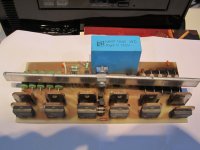
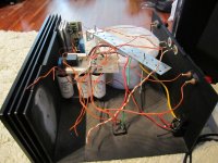
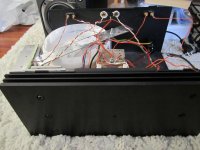
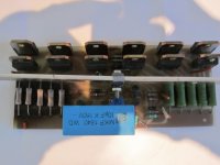
When i opened it ... okei better some pictures to describe the execution.
I have only a very general comment.
While i understand the sane philosphy to keep a short path for signal sometimes it seems to me that designers exaggerate it a little.
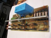
The channel PCBs are very small and all the parts are very closely spaced
This is in general a nightmare for maintenance
They should have used a pcb design like this one for instance ... long and narrow instead of short and narrow.
I see many output transistors paralleled.
So my feeling is that the project is ok but the lay-out could have been better.
But without schematic it is impossible to proceed.
I will try to take some photo anyway.
I'm wodering if the Doxa 70 scheme is the same?
I have no clue ... i think i will dismantle it in the next weekend and take a picture of the pcbs
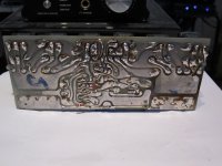
I have very basic knowledge but there is a small rule, called the ohm law that after all these years is still very fashionable i believe.
I would expect big sections where there are big currents ... and this is not the case here with very small wires for voltage supply after the mighty (very big indeed) transformer and also thin cables connected to speakers outputs.
But i know i am a little naive.
Kind regards, gino
Last edited:
Can you give me your Email address? Just send a PM
Sent !
Regards, gino
Good morning Guys !
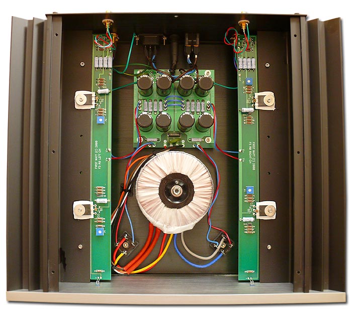
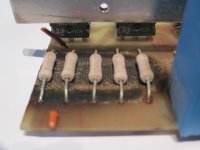
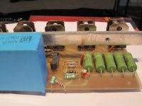
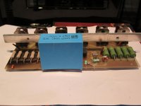
some pictures just to show that i am not the only "dog" around ...
some pictures just to show that i am not the only "dog" around ...
Attachments

it is a real pity that the schematic is not available
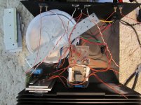
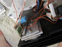
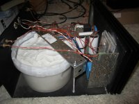
It worked just one day and hot flace plate aside the sound was convincing
I am still not convinced that class A is mandatory for good sound and personally i think that the power supply is th strong point of this amp ... i can only imagine a 600-700 VA transformer and nice Rifa ps caps ... they look of the good type
If anyone has any information i will be grateful
Thanks and regards, gino
I would remove one of the trannies on the left side to see if it isn't a faulty one.
Hi and thanks a lot for the valuable advice.
I am thinking to save at least the power supply
I will measure the voltage rails and look for some kit using the same +/-VDC.
A clean one ...
I am quite convinced that the good sound was coming from the PS.
Any decent AB design will sound at least decent
I am not a fan of Class A given that very good AB designs do exist ... so why waste energy ?
I also would like a single output pair design ... maybe with a pair of 200 W bjts
Low voltage rails and high current ... this is the secret
personaly I think this isn't a original one but a DIY clone
Unfortunately i have no info about the original
Even as a prototype is a little rudimentally built
Anyway on the front plate there is indeed the DOXA name engraved.
I hope some kind Norwegian guy will jump in the 3D with useful information.
Thanks a lot again, gino
Those caps are they Rifas?
Edit : Yes, they are looked a few posts back
Yes ! and i have a great opinion of them ... but i am afraid they are old .. i will check for the date
I like the fact that they are terminated with screw ... i would make this mandatory by law ...
Can you test the PSU without the amp connected?
I think so ... i sincerely hope is not the transformer
My plan would be to wait another week just to see if i can find a schematic
If not dispose the two pcbs and look for a kit.
No class A ... no mosfet output ... just a single output pair ... the easiest to build around with decent sound.
I will be using just few watts at max so i could use the face plate as heatsink
But in the meantime i will measure the voltage rails ...
i hope that the short circuit is in the removed pcb.
And in the end maybe i will discover that is the relais ...
and that the amp was fine Thanks again, gino
- Status
- This old topic is closed. If you want to reopen this topic, contact a moderator using the "Report Post" button.
- Home
- Amplifiers
- Solid State
- Doxa 40 power amp - info required