I've had this Speakercraft amp for a while and just had the lid off to fix a dry joint. Whilst poking around, I was reminded of some components that don't look in good shape.
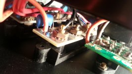
There are two stereo sets of binding post on the rear panel. Where the binding posts pass through the chassis, there are two small pcbs with what looks like a resistor and capacitor in series with each other - these are connected across each binding post in parallel.
The resistors look decayed and the cabling near by has melted a little. So something has been hot. The amplifier works fine, but I hope for some advise on whether these components should be replaced or can they be safety removed. I read that output filters can degrade the sound and in some circumstances can be removed.
So is it advisable that these can be removed if they are indeed filters??
Attachments
To help you with specific answers, others need specific details like the model number so the schematic can be searched to find out what it is your pic is showing. Otherwise, posting the relevant part of the schematic or a link to it is good way to get help. Unfortunately, late model schematics are seldom available free on the 'net.
As a guess from the size of the resistor and capacitor, it seems the output filter you refer to is commonly called the Zobel network - usually made up of a 0.1uF film capacitor and around 10 ohm resistor in series from the output (+) to (-) and is a "one size fits all" device. It's not good or normal to fit this remotely from the power amplifier PCB itself but anything is possible from some manufacturers and Speakercraft product is certainly unusual compared to older and mainstream class AB amplifiers, as I understand this amplifier likely is.
If you would confirm the values or markings of those parts, you should have your answer but also a warning of dire consequences for the amplifier's stability if they have failed or you remove them. Expect at least a 100V rated polyester cap and 1W film resistor there, which appears to be the case.
It isn't an option to remove this filter since doing so could lead to the amplifier self destructing. Class AB amplifiers usually do show instability and fairly quickly without a means of damping internal oscillation and interaction with the load, like a Zobel network. If there is damage, replace the parts with like values and ratings but don't omit them.
Do not remove safety features on your amp
Damage in the parts of zobel means only a few of things
One, that you make excessive use of high in your set up ( treble is always at quiet big level ) meaning that either your speakers or your ears are not happy with a reasonable amount of high
Two, in the installation there is a flaw that decrease the bandwidth of the signal> forcing you to add more high > forcing the zobel
Three, speaker cables are too long , two wrong ,and/or load is too capacitive and zobel struggles to suppress the products of this installation
Replace the worn parts but most of all find out what is wrong
Kind regards
Sakis
Thank you all for your replies.
Ian you were right on many counts...
I've hunted for a schematic on the web and turned up nothing. I tried calling Speakercraft technical department; they were unable to provide a schematic or offer advice on component values required.
I had another chance to look inside it and have a few more details.
The amp is a Speakercraft - BB2125.
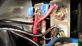
At the output speaker terminals, the capacitors are marked: IF 0.047k PMD 160V
The resistors are so badly damaged that I am unable to read them though can see a red ring and a gold ring on the outer edges of one resistor.
I tired measuring the resistors (in circuit) and read the following:
Speaker A Left: 20M Ohms
Speaker A Right: 15 Ohms
Speaker B Left: 26 Ohms
Speaker B Right: 2.4M Ohms
OK, I would like to keep the safety feature and repair if the parts if possible. Though as above I am unsure o the value of resistors (should they all read 15Ohms which is close to the value predicted by Ian)?
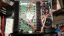
As for what is wrong, the amp came to me in this condition but seems to play fine. There are only a few mV of DC on the speaker terminals. But on the main amplifier board there is another pair of filters (or similar components) that are also showing similar signs of overheating. -I've attached a picture in the pdf.
This other filter is located on what looks like the main DC rail power supplies near where they connect to the main amplifier PCB.
Surely too much coincidence that identical looking components else where on the board look smoked too? Would this indicate a power supply issue?
Ian you were right on many counts...
I've hunted for a schematic on the web and turned up nothing. I tried calling Speakercraft technical department; they were unable to provide a schematic or offer advice on component values required.
I had another chance to look inside it and have a few more details.
The amp is a Speakercraft - BB2125.
At the output speaker terminals, the capacitors are marked: IF 0.047k PMD 160V
The resistors are so badly damaged that I am unable to read them though can see a red ring and a gold ring on the outer edges of one resistor.
I tired measuring the resistors (in circuit) and read the following:
Speaker A Left: 20M Ohms
Speaker A Right: 15 Ohms
Speaker B Left: 26 Ohms
Speaker B Right: 2.4M Ohms
Do not remove safety features on your amp
Replace the worn parts but most of all find out what is wrong
OK, I would like to keep the safety feature and repair if the parts if possible. Though as above I am unsure o the value of resistors (should they all read 15Ohms which is close to the value predicted by Ian)?
As for what is wrong, the amp came to me in this condition but seems to play fine. There are only a few mV of DC on the speaker terminals. But on the main amplifier board there is another pair of filters (or similar components) that are also showing similar signs of overheating. -I've attached a picture in the pdf.
This other filter is located on what looks like the main DC rail power supplies near where they connect to the main amplifier PCB.
Surely too much coincidence that identical looking components else where on the board look smoked too? Would this indicate a power supply issue?
Attachments
Hi,
It would be very odd for the Zobel to be affected by A/B
speaker switching and no way are your readings across
the resistors for A and B correct without a rather large
reassessment of what they are intended to do.
e.g. 20M across an output resistor = open fried,
15R across the same resistor switched = that
another parallel component must now be involved.
A/B switching is very unusual, usually A or A+B
(series or parallel), or A / B / A+B (S or P).
rgds, sreten.
Last edited:
The zobel network is there to provide a flatter response for the amplifier at higher frequencies. The speaker impedance goes up at higher frequencies and the zobel compensates for this giving a more constant load across the audio band.
I have never fitted one to stop oscillation in my designs.
If there is oscillation it can usually be stopped at the VAS stage with a VAS transistor B-C capacitor of around 100pf.
I recently overhauled a Maplin 225WRMS amplifier.
I fit brand new transistors on the outputs and the amp oscillated badly.
I checked the new transistors on a transistor tester and the gain was huge compared to the spec of the original transistors.
I fixed the problem by slightly increasing the capacitor in the VAS stage.
Last edited:
Thanks Sreten.
There is no A/B speaker switch, both speaker outputs are wired in parallel from the same point on the main board. There is a 4 or 8 ohm speaker selector though.
So the high reading resistors are likely to be caput?
All the resistors look damaged and some caps are showing signs of heat from the resistors.
Hi,
It would be very odd for the Zobel to be affected by A/B
speaker switching and no way are your readings across
the resistors for A and B correct without a rather large
reassessment of what they are intended to do.
A/B switching is very unusual, usually A or A+B
(series or parallel), or A / B / A+B (S or P).
rgds, sreten.
There is no A/B speaker switch, both speaker outputs are wired in parallel from the same point on the main board. There is a 4 or 8 ohm speaker selector though.
20M across an output resistor = open fried,
15R across the same resistor switched = that
another parallel component must now be involved.
So the high reading resistors are likely to be caput?
All the resistors look damaged and some caps are showing signs of heat from the resistors.
I have never fitted one to stop oscillation in my designs.
If there is oscillation it can usually be stopped at the VAS stage with a VAS transistor B-C capacitor of around 100pf.
Presumably the zobel is not now functioning as it should even though sounds are still coming out. Not sure about oscillation, if I can find out how to check for it I could dig out the scope to see.
Thanks Sreten.
There is no A/B speaker switch, both speaker outputs are wired in parallel from
the same point on the main board. There is a 4 or 8 ohm speaker selector though.
I tired measuring the resistors (in circuit) and read the following:
Speaker A Left: 20M Ohms
Speaker A Right: 15 Ohms
Speaker B Left: 26 Ohms
Speaker B Right: 2.4M Ohms
Hi, well make some sense of what your saying, because it doesn't, rgds, sreten.
Last edited:
Hi, well make some sense of what your saying, because it doesn't, rgds, sreten.
There are four pairs of speaker terminals (4 red terminals, 4 black).
There isn't any facility to switch between sets of speakers.
Each speaker output pair has a resistor and capacitor across it (Zobel).
The resistance readings above are taken by measuring the resistors in the Zobel. My interpretation from your suggestion and others' (but which I guess is wrong) is:
Speaker A Left: 20M Ohms [resistor fried]
Speaker A Right: 15 Ohms [resistor ok]
Speaker B Left: 26 Ohms [resistor ok?]
Speaker B Right: 2.4M Ohms [resistor fried]
Hope that make sense otherwise I missed your point?
Presumably the zobel is not now functioning as it should even though sounds are still coming out. Not sure about oscillation, if I can find out how to check for it I could dig out the scope to see.
The amplifier will still function without it.
Some designs don't even bother with a Zobel network.
The Zobel cancels out the inductive load of the speaker.
This makes the load on the amplifier more like a resistance.
Look for high frequency oscillation on the output signal.
The oscillation has occurred in the past and TBH, we can't really say what this amplifier has been subjected to that could have brought it on as strongly and sustained as to fry the resistors. However, seeing they are so identically burnt, both on the main PCB and at the output terminals, this is surely a fault in common with both channels. That suggests to me a tinkerer attempting to bridge (or even parallel) the channels, as we often see asked here in the help threads.
When the smoke began to rise, a dismayed tinkerer disposed of the remains and here they are. Any other guesses as to how you get identical damage?
I suspect there is now no reason for oscillation to continue if the amp is restored to its previous working condition. To see oscillation on the scope, simply couple to a low impedance point such as the output terminals or the output node on the power amplifier PCB, remembering that conventional oscilloscope ground is connected to protective earth. Your power amplifier may be double insulated or the signal ground floating but I can't tell whether this will be a problem if you connect the PE of your scope lead to your amplifier's signal ground terminal. Maybe a high voltage film cap of say, 0.1uF between them would be safer. Amplitude could be anywhere from mV to V.
Oscillation is no different to any signal in the measuring, but there is no corresponding input signal. Usually, it is orders of frequency higher than audio. Try looking for anything from 100 kHz - 1 MHz in the mV to volts range even, in the first look then, if your 'scope is capable, look around 20 MHz for signs of spurious, maybe fleeting signals. If you have a sinewave generator, it can be used as an input to trigger oscillation when nothing is apparent. You may need to press the amplitude up to clipping level to provoke anything this way but as long as it's unloaded, that should not be any problem. Look for wriggles on the sinewave at peaks or use the square wave to observe what happens to overshoot as you switch ranges though this is a fair sized topic on its own. Google and Youtube are your friend.
Re: the values: I'm also confused why speakers B have different value networks across them to A, unless this is some cheapskate way of distributing the damping when speakers are in parallel. From what I can tell, if the film caps on the main PCB are 0.047uF too, the resistors should all be around 10R. Those at the output terminal probably are 15R, if the zobels and B terminals are always in parallel as you say. Certainly, anything like IM has fried. Take a closer look at colour bands (such as they are) and see what you can deduce for 4 band codes. Otherwise you are just going to have to scour the neighbourhood and hustle up a similar amp. to look at.
Last edited:
The Zobel can be at the amplifier output, or at the amplifier's Speaker terminals.
Neville Thiele showed that adding an R||L to the amplifier output helped stabilise power amplifiers.
He also showed that the R+C (the Zobel part) could be fixed either before the R||L or after the R||L.
Many amplifiers rely on the load of the Zobel to stabilise them.
This load ONLY becomes effective at high frequencies. Typically > 30kHz
For the load to be effective the inductance in the route from output devices through to the Power Ground and then back to the Output devices MUST BE KEPT SMALL.
This demands that the route should be very short and the LOOP AREA of the route MUST BE KEPT SMALL.
This means that the Zobel AFTER the R||L does not help stabilise the amplifier because the inductance is too high. But it does help with other instabilities when combined with the R||L.
Some are now advocating a Pi version of the Thiele Network.
This is a R+C at the output devices.
An R||L in the route from amp to terminals
And an extra R+C across the terminals.
It seems that your amp has R+C at the amp and again at the terminals. If there is also an R||L between them, then you have the Pi version of the Thiele Network.
Replace the 0.047uF (47nF) caps with new fairly high voltage MKT capacitors. 150Vac or higher.
Replace the resistors with power resistors, metal oxide or carbon composition are good for this duty. Aim for around 3W
the red and gold at opposite ends tells us that the gold end = +-5%
the red end tells us that the resistor value started with a 2.
It could have been 22r.
When both R+C are fitted the amplifier sees them as parallel loads. i.e. the amp sees 11r+94nF
This is close to a fairly normal Zobel value for many amplifiers.
BTW,
full power testing at HF is what blows output Zobels.
Some operators that think they know what they are doing, often think that checking amplifiers for full power at 50kHz and 100kHz must be good.
Little do they realise that the next time they power up, they do so into dead Zobels !
Last edited:
Not being exactly a textbook design, I'd say there was an output coil's worth of inductance in that cable-tied bundle of output leads. Perhaps that spoils the small loop requirement.
I'm also dumbfounded Andrew, that anyone would take it upon themselves as an operator (presumably professional) to test anything outside its required bandwidth, given that they would have the skills and resources to do this properly and understand the consequences if not rechecked afterwards. A technician repairer or maintenance tech. doesn't need to anything like this, so what kind of cowboy can stay employed doing that kind of testing and damage?
Then again, if you are politely referring to self-styled audio lunatics, I guess anything is possible and the more fantastic the results, the greater the peer respect.
Exactly...............Then again, if you are politely referring to self-styled audio lunatics, I guess anything is possible and the more fantastic the results, the greater the peer respect.
I had other descriptors in my comment and thought again and took them out.
I get hammered repeatedly for what I think is OK, but others have their views/opinions as well.
The bandwidth of many amplifiers, even chipamps is well over 50kHz and some go above 1MHz.
Power testing into dummy loads @ > 20kHz is not unknown.
I do it.
But I watch, feel, check what my Zobel resistors are getting up to while I do it.
Half power bandwidth NEEDS full power testing while checking the distortion. That takes time and time enough for Zobel resistors to be damaged if not destroyed.
To see oscillation on the scope, simply couple to a low impedance point such as the output terminals or the output node on the power amplifier PCB
Try looking for anything from 100 kHz - 1 MHz in the mV to volts range even, in the first look then, if your 'scope is capable, look around 20 MHz for signs of spurious, maybe fleeting signals. If you have a sinewave generator, it can be used as an input to trigger oscillation when nothing is apparent. You may need to press the amplitude up to clipping level to provoke anything this way but as long as it's unloaded, that should not be any problem. Look for wriggles on the sinewave at peaks or use the square wave to observe what happens to overshoot as you switch ranges though this is a fair sized topic on its own. Google and Youtube are your friend.
Re: the values: I'm also confused why speakers B have different value networks across them to A, unless this is some cheapskate way of distributing the damping when speakers are in parallel.
Many thanks for this. I did as you suggested and connected the 'scope to the output terminals (earth was same as at chassis ground). The waveform wasn't what I would call clean but when I checked the output from the source (PC based signal generator feeding into digital crossover DAC), I saw some noise on the waveform. The amplifier waveform matched the source including noise. At low volume levels the noisy waveforms are as big as the sine waves. Guess this is another area that needs investigation, seems to me to be noisy ground. For information, this is not the same source that I normally use with the amplifier in discussion here. So, I don't think the amplifier is oscillating.
Replace the 0.047uF (47nF) caps with new fairly high voltage MKT capacitors. 150Vac or higher.
Replace the resistors with power resistors, metal oxide or carbon composition are good for this duty. Aim for around 3W
the red and gold at opposite ends tells us that the gold end = +-5%
the red end tells us that the resistor value started with a 2.
It could have been 22r.
Thank you Andrew. I have ordered new MKT capacitors and some 3W metal oxide resistors. I looked at the only two bands that remain on the resistors and, although I consider my eye sight to be good, I can not discern if the colour is brown or red, I think the colour has changed with the heat.
I went with 15ohms. Hope this will be ok.
I plan to get the amplifier back into a safe state sometime next week once the bits arrive.
Thanks to all for advice.
Seems like a reasonable plan. You might have a quick look at Sakis' recent scope pics with a function generator input and note the thickened trace of the pic showing obvious clipping. This is one sign of instability, provoked I assume, by the clipping events at the the positive peak. Look at the wriggles on the negative swing of the triangle trace too. You can see the point of using a steady or repeated cycle waveform for this kind of observation.
Note this is just an illustration, I'm not suggesting this will appear similar to any oscillation you may see in your amplifier.
http://www.diyaudio.com/forums/solid-state/259930-solid-state-joke.html
Note this is just an illustration, I'm not suggesting this will appear similar to any oscillation you may see in your amplifier.
http://www.diyaudio.com/forums/solid-state/259930-solid-state-joke.html
- Status
- This old topic is closed. If you want to reopen this topic, contact a moderator using the "Report Post" button.
- Home
- Amplifiers
- Solid State
- Is this a filter at amplifer output and can I remove it?