Sanken 2SA1295/2SC3264
I am heading in the direction of buying a pair of Sanken 2SA1295($6.55)/2SC3264($6.80) from Digikey.
Too many fakes of the existing Toshiba being offered along with the NTE products. The $2 and $3 NTE chips from China can not be genuine.
I know this unit is not worth the investment but I look at it as a learning project.
Any thoughts or comments?
Last edited:
removed output IC's on one channel. Reconnected secondary, Using DLB powered amp up and the bulb glowed brightly and then decreased. Relay clicks.The bulb still seems to glow substantially. The amp did power up without blowing a fuse. Connected speaker up to see if any evidence of output on the one good channel and no evidence.
Test the assembly in simple stages.
Power on via Mains Bulb Tester until you haved proved that all modules and all wiring is all operating correctly.
First test the transformer alone.
Then test the transformer plus rectifier.
Then test the transformer plus rectifier plus one pair of smoothing capacitors. Use a pair of small (around 100uF to 470uF) electrolytics with a voltage rating above what the previous test showed as output voltage.
Then test the transformer plus rectifier plus original smoothing capacitors.
Then test the transformer plus rectifier plus original smoothing capacitors plus one amplifier.
Remove that amplifier and repeat the test with the other amplifier.
Then test the transformer plus rectifier plus original smoothing capacitors plus both amplifiers.
Then test the transformer plus rectifier plus original smoothing capacitors plus both amplifiers plus one speaker or dummy load.
Then test the transformer plus rectifier plus original smoothing capacitors plus both amplifiers plus both speakers or dummy loads.
AndrewT, This receiver has one integrated regulator, driver, and power circuit board. The only hard wiring that can be removed is the AC from the transformer secondary.
I have confirmed the transformer secondary for the amplifier section is not shorted or open by removing load upstream. Cut wires.
Then removed output IC's(one PNP and one NPN, MT200 case) on one channel that had hard short emitter to collector, removed hard short, the receiver can now be powered on with DLB in place. The dimness of the bulb after capacitor charge up makes me suspicious of a soft short?
Now that the side that had the hard short is powered I can measure voltage on rails, measure voltage at transistor bases, etc?
To test section by section I assume the transistor upstream must be unsoldered and removed from the board?
tested the transistor rail voltages they are ok. checked out the two transistors one stage back from the shorted output IC's and they check ok. ordered a pair of the Sanken transistors from Newark.
did power the receiver with out the output IC's on one side installed using straight 120 VAC without the DLB in place and it was ok.
did power the receiver with out the output IC's on one side installed using straight 120 VAC without the DLB in place and it was ok.
I am assuming without the output IC's in place on one channel that it goes in to protect mode?
Can anyone help describe how the self protect mode works?
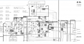
I see IC801 with nine inputs does the function.
There is a large relay 801 near IC801 that is clicking. It appears it opens or closes the final stage output.
The ±48VDC rail voltages are present.
There are two inputs on IC801 monitoring output of final stage...without the output IC's on one channel in place, the IC is not happy?
Can anyone help describe how the self protect mode works?
I see IC801 with nine inputs does the function.
There is a large relay 801 near IC801 that is clicking. It appears it opens or closes the final stage output.
The ±48VDC rail voltages are present.
There are two inputs on IC801 monitoring output of final stage...without the output IC's on one channel in place, the IC is not happy?
Attachments
Last edited:
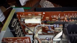
replaced the output IC'S and the unit is up and running. I used the Sanken IC's. I will have to comment at a later date when I get time to listen well to see if there is any difference in the sound of the original ICS on one channel and the replacement IC's on the other.
the volume level indicators I'm not working so I will fool with that next. Any Ideas?
the volume level indicators I'm not working so I will fool with that next. Any Ideas?
The volume range indicator, as it is called on the schematic, is a plastic sheet that rotates using the volume motor shaft. It is a belt. Inside the housing is a #44 6v .25 amp bulb. The bulb was blown waiting for a replacement. It was difficult to get to but will post images of this contraption.
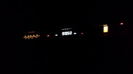
I was just excited to get the bulb out of the volume range assembly....it was very tight. Purchased 2 pieces of new GE vintage 6.3V .25A bulbs. Should be here Friday....will post image of it lit up. I have been slowly freeing up the analog frequency meter. It was a bit sticky from sitting.
I will be buttoning this up and be moving on to a Technics SU V9. These pieces were in group of equipment that was given to me. The whole group comprised of:
Technics SA 626 Receiver Operating
Technics SU V9 Integrated Power Amp Powers up, need to repair input selector remote control cable
Technics Audio Timer SH 4020 Operating
ADC SS-315 Sound Shaper Equalizer
AIWA AD-6550 Cassette Deck
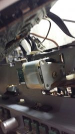
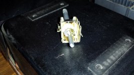
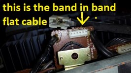
Really want to get this band in band cable assembly used to remotely actuate the input selector slider switch on the SU V9. This is a pretty nice looking piece and the glass door is there and operating.
Technics SA 626 Receiver Operating
Technics SU V9 Integrated Power Amp Powers up, need to repair input selector remote control cable
Technics Audio Timer SH 4020 Operating
ADC SS-315 Sound Shaper Equalizer
AIWA AD-6550 Cassette Deck
Really want to get this band in band cable assembly used to remotely actuate the input selector slider switch on the SU V9. This is a pretty nice looking piece and the glass door is there and operating.
Images of the input selector switch SU V9, band in band remote cable, and the input selector switch on the circuit card. If the slider switch freezes and the input selector switch is forced it strips the inner band that remotely actuates the slider switch.
Attachments
Last edited:
- Status
- This old topic is closed. If you want to reopen this topic, contact a moderator using the "Report Post" button.
- Home
- Amplifiers
- Solid State
- Technics SA 626 blowing fuse before transformer