All, Sorry for the *noob* question, but I've been working on this guy for quite a few months now and I'm not getting anywhere.
I've got a NAD 2100 Power Envelope amp, and it's working well and sounds great. I recapped EVERY electrolytic (Nichicon FG), changed out the preamp to an LM4562, pulled out some Sanken output drivers that a previous owner had once repaired the amp with (I replaced them with Toshiba 2SA1943/2SC5200), and set everything up as best I can.
My issue is with the DC offset. One channel is right at 110mV at turn on and around 90mV once it warms up. The second channel is around 40mV.
This is not technically outside of the service manual specs, but I'd still like to get it down and I don't know how. I read one thread that suggested changing the input resistance (R403), so I put in a pot there. It did make a MINOR difference, but only down to about 70mV and only when the resistance lowered to about 1K or less. That was too low for my taste, so it went back to 10K.
One thing to note: the DC offset measured exactly the same BEFORE I did any of the re-cap or transistor changes. So, I know my changes did not affect anything regarding this issue.
Here's a snapshot of one of the amp's channels:
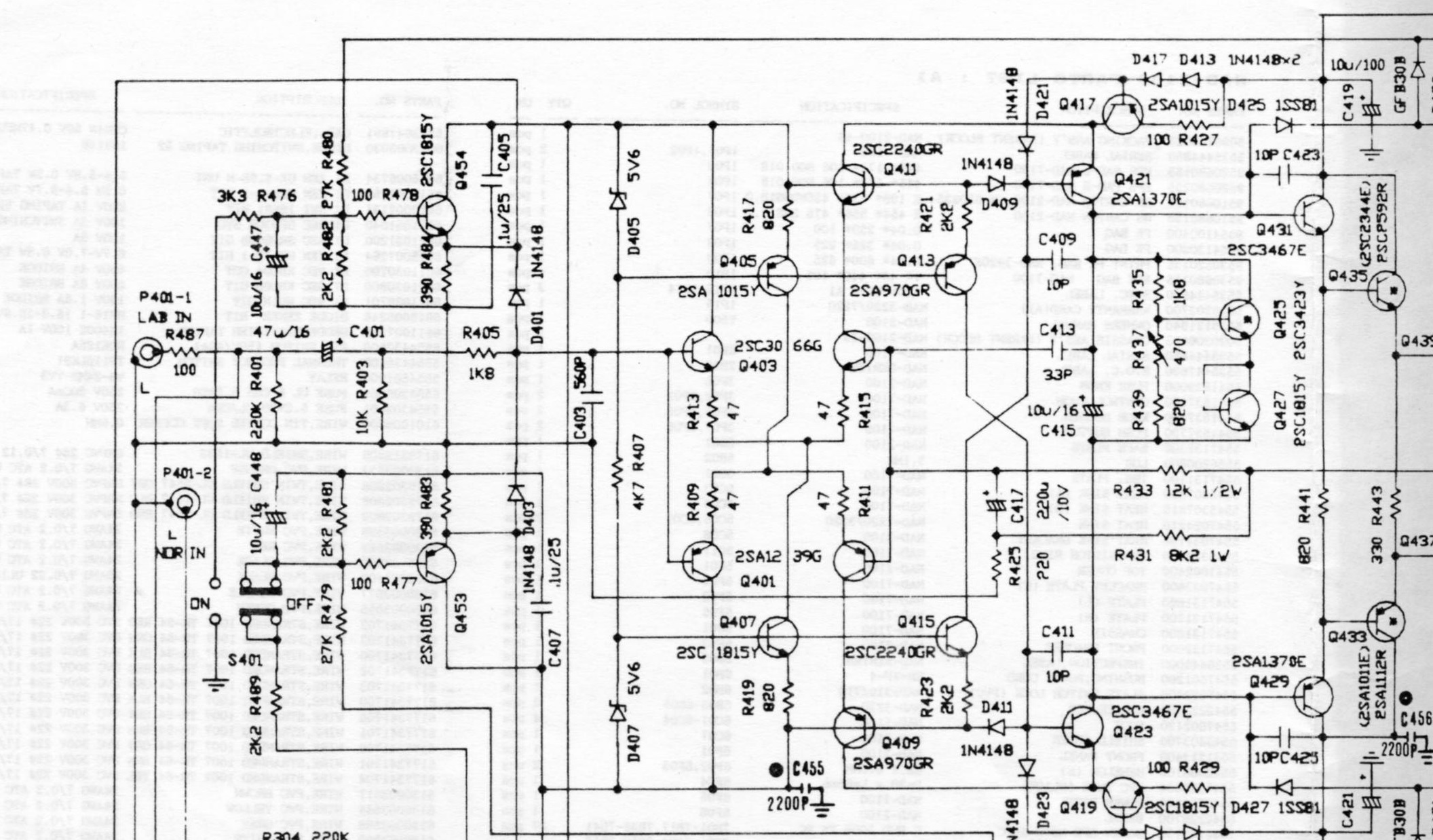
Here's are two different links to the full service manual. The second one is a better copy, but it requires you to register:
NAD 2100 Service Manual free download, schematics, eeprom, repair info for electronics
NAD 2100 Manual - Monitor Series Power Amplifier - HiFi Engine
Any help and guidance you guys can provide would be greatly appreciated. Thanks!
I've got a NAD 2100 Power Envelope amp, and it's working well and sounds great. I recapped EVERY electrolytic (Nichicon FG), changed out the preamp to an LM4562, pulled out some Sanken output drivers that a previous owner had once repaired the amp with (I replaced them with Toshiba 2SA1943/2SC5200), and set everything up as best I can.
My issue is with the DC offset. One channel is right at 110mV at turn on and around 90mV once it warms up. The second channel is around 40mV.
This is not technically outside of the service manual specs, but I'd still like to get it down and I don't know how. I read one thread that suggested changing the input resistance (R403), so I put in a pot there. It did make a MINOR difference, but only down to about 70mV and only when the resistance lowered to about 1K or less. That was too low for my taste, so it went back to 10K.
One thing to note: the DC offset measured exactly the same BEFORE I did any of the re-cap or transistor changes. So, I know my changes did not affect anything regarding this issue.
Here's a snapshot of one of the amp's channels:
Here's are two different links to the full service manual. The second one is a better copy, but it requires you to register:
NAD 2100 Service Manual free download, schematics, eeprom, repair info for electronics
NAD 2100 Manual - Monitor Series Power Amplifier - HiFi Engine
Any help and guidance you guys can provide would be greatly appreciated. Thanks!
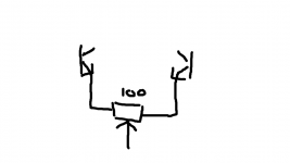
Like this
I'll try and give that a shot. I assume that the center pole of the 100-ohm pot will feed the collector of "tapped" transistor?
For example, if I replace R413/R415 with the 100-ohm pot, then the collector of Q407 will be fed by the center pole?
Thanks for your suggestion. Any help is welcome. I was certainly surprised to not see a DC offset adjustment on this amp.
Yeah, but I don't remember exactly. Wasn't it something with additional transformer
windings, giving a higher secondary voltages, to compete with PSU sag at load?
Sadly I wasn't able to find any specific answer.
However, if it worked this way, I don't think it has been a principle worth staying
awake at night. Hard to beat a real solid PSU.
windings, giving a higher secondary voltages, to compete with PSU sag at load?
Sadly I wasn't able to find any specific answer.
However, if it worked this way, I don't think it has been a principle worth staying
awake at night. Hard to beat a real solid PSU.
Sorry, I'm totally off topic :
I found adding 1500 uf Panasonic FC with two copper wires (from a speaker Self) on the littlier main caps had a great improvement !
Put myself KZ muse 100V but the first stage (not the pre) with little Panasonics FM caps. For the pre section caps were changed but the two first Lelon which were great here ; put after mainly Silmic I (not the II !), I keeped all the green radial caps and putted 2 Silmic I also on the pots pcb !
Wow... very nice amps, I agree ! Tones are even better, musicality increase, and bass are better, not dull anymore.... drive nicely and with energy without harchness my Kef 104/2 ref ! (PS : I changed the 2 x 10K uF Elna caps for Jamicon...after ten years...)
I had to try the oap Mooly advised and that you puted : LM4562 ! (also BB2604 ! )
But change the 5K volume pots (one are very tired and shutdown alone sometimes !) : Could you an idea were can find such pot value please ?
Last edited:
Pots should be readily available then as long as they physically fit. Conductive plastic types are pretty decent and cost effective.
PC16ECO4K7A - OMEG - POTENTIOMETER, LIN 4K7 | CPC From This Range
PC16ECO4K7B - OMEG - POTENTIOMETER, LOG 4K7 | CPC From This Range
PC16ECO4K7A - OMEG - POTENTIOMETER, LIN 4K7 | CPC From This Range
PC16ECO4K7B - OMEG - POTENTIOMETER, LOG 4K7 | CPC From This Range
Thanks Molly,
the pots are the old way : with a cut in the midle of the "harm" : 4 cm long... exactly like this one (but this one is a 5K linear, i surmise the Nad to use log pots !) : potentiomtre mono vrb-100m5 5k
the pots are the old way : with a cut in the midle of the "harm" : 4 cm long... exactly like this one (but this one is a 5K linear, i surmise the Nad to use log pots !) : potentiomtre mono vrb-100m5 5k
You could always add a resistor to fake a log law if you wanted but tbh, its not so vital a thing really.
See changing the law of a pot,
Potentiometers (Beginners' Guide to Pots)
See changing the law of a pot,
Potentiometers (Beginners' Guide to Pots)
 thanks Molly
Mooly - I just wanted to follow up and say THANKS! Your idea worked great. I replaced the R409/R411 pair with the pot and was able to adjust the offset. When I got it down to 40mV offset, I stopped and pulled the pot out. The measured values stand at R409 = 60ohm and R411 = 38ohm. Given the rather large imbalance (typically 47-ohm each), does this indicate anything more troublesome, or can I keep those values as is and be happy?
Thanks again!
__________________
Eldam, I have two suggestions for you:
First, I would try and use a contact cleaner like Caig's Deoxit D5 or F5. This will help clean the pots and typically gets my scratchy or noisy pots working well again.
Second, if you have a volume control in your preamp, you can simply use the "LAB" input on the amplifier instead of the "NORMAL" input. The "LAB" input will bypass the entire preamp board with the volume controls and op-amp. Enjoy!
Last edited:
Your welcome. Pleased to hear it worked OK ") and you can keep those values and be happy.
and you can keep those values and be happy.
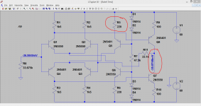
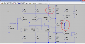
(you could possibly get it more balanced still by seeing how sensitive the design was to such things as minor changes in those two zener voltages or more specifically the current in the two 820 ohm resistors R417 and R419. Are they equal ? Just measure voltage across the resistors to check. Tweaking either of those would also trim the offset. This shows a similar front end. Look at the offset voltage and the effect of altering the 220 ohm. Its very similar to yours. )
and you can keep those values and be happy.(you could possibly get it more balanced still by seeing how sensitive the design was to such things as minor changes in those two zener voltages or more specifically the current in the two 820 ohm resistors R417 and R419. Are they equal ? Just measure voltage across the resistors to check. Tweaking either of those would also trim the offset. This shows a similar front end. Look at the offset voltage and the effect of altering the 220 ohm. Its very similar to yours. )
Attachments
Thanks Tyger,
If if can't find cheap pots or will not go with Mooly option (which seems a better solution with a 2 euros pot), I will try to clean... unluckily here all those cleaner products are more expensive than a cheap pot !
About the "lab in" : yes I know that. But here it's a second system and I found the pre option just good for it and love the fine two mono pots for fine balance setup ! The fine re caped ps stage adds also a great improvement and I just ask myself about the opportunity to rep^lace the bad coax wires for signals between back and front panels with a good cheap Mogami e.g. ! Not too expensive in relation to the global sound quality of this little nice amps.... I'm again the tweakings which are more expensive than the device : here all stay reasonable : just oap, fews caps needed after 20 years of loyal service !
Try to add the two 1500uF FC caps and tell me : you won't believe it ! A good option can be also KZ muse 100V nears the power transitors... not expensive, but first the two FC added to the 10K uf is a huge improvement !
Mooly, the current across the two 820's is very close (4.96V versus 4.95V) now, but I've already used the pot to adjust the offset. I see how adjusting this could affect the DC offset as well. Thanks again for this idea!
My only issue now is the fact that one of my two main power supply caps keeps bulging (slightly on the top of the cap, not to the point of rupture). I've replaced it twice now, and the caps seem to keep bulging. When I pull out the cap, it measures within tolerance, but I had some extras so I replaced it. I can't keep replacing $10 caps though. It's always the same capacitor (C507, which is the main 80V power supply cap for the +Vh rail). I've measured 71.2V across it during operation, and I've never seen it vary. C508 exhibits no such bulging, and there is no real heat in the area. Any ideas on that?
Eldam, are you saying to place two 1500uF FC caps across C509. C510?
Hi,
IIRC C509/10: the two littlier 10K uF caps : Brandnews out of the boxes when I buyed it off-shelves they were Elna 50V... the two others are with golded letters and have higher case !
But I believe this tip can affect positivly the two inputs mode... choose the couple of 10K uF caps you use ! This DIY is not very clean : long wired plain copper leads add a lot of inductance... but it just sounds greater at home by a large margin, not a poor 220 uf but 1500 uf : FC panasonic 50V ! I didn't try the FM serie because no Pi filtering here so a lower ESR was prefered. Notice I didn't check with no more serious devices than my ears (no scope at home ! )
- Status
- This old topic is closed. If you want to reopen this topic, contact a moderator using the "Report Post" button.
- Home
- Amplifiers
- Solid State
- NAD 2100 DC Offset