As if one output transistor were blown?so far there's a huge offset and loud hum.
Disconnect speaker and measure voltage at the speaker out terminals.
Attached are some measurements. It's from one channel only as the other channel is now a burned mess.
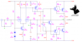
Output offset is around 1.1V.
Notice that the grid leak resistor on the input tube is grounded through R17 (10K) as marked by point A. This is the design of the PCB i'm using. I don't think this would cause the offset though..
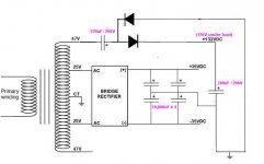
Attached also is the PS schematic. The hum is really like mains hum.. so it's either 120V ripples or bad grounding. I will attach some wiring pics after this.
Output offset is around 1.1V.
Notice that the grid leak resistor on the input tube is grounded through R17 (10K) as marked by point A. This is the design of the PCB i'm using. I don't think this would cause the offset though..
Attached also is the PS schematic. The hum is really like mains hum.. so it's either 120V ripples or bad grounding. I will attach some wiring pics after this.
Attachments
Member
Joined 2009
Paid Member
Initial thought - voltages look reasonable. I'd probably run the output with less current, something closer to 20mV across R14/15 although that's a fine tune and ripe for a different discussion about best bias for CFP output. You have about 2mA through R17 which looks good. You have different current flows through each tube (V1a and V1b) which is partly why you have a dc-offset. You need to adjust that out by adjusting R17 (changing the LTP tail current will change their balance). VAS current around 9mA, probably higher than you need, something closer to 5mA to 6mA may be fine and allow Q1 to run cooler (increase R8/9).
The hum is most likely to be from the power rails - oscillations would be inaudible as said above, but they can result in output devices blowing up quickly.
The hum is most likely to be from the power rails - oscillations would be inaudible as said above, but they can result in output devices blowing up quickly.
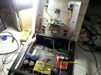
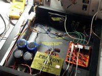
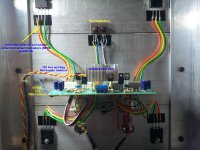
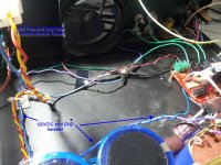
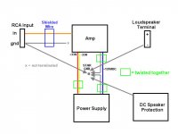
Wiring pics attached.
I'm questioning whether me twisting these wires together is a good idea:
1. 33VDC positive and negative rails supply twisted together
2. 120VDC and PS Ground twisted together
If one can show me good guide on star grounding, that might help. On my build, the following grounds meet at the star point:
1. Amplifier PCB Ground
2. Power Supply Ground
3. Loudspeaker Terminal Ground
4. Speaker Protector Ground
5. Input RCA Ground (from input RCA to amplifier PCB is a shielded pair but only one side of the shield/screen is grounded) --> bad idea?
Attachments
You have about 2mA through R17 which looks good
710mV / 33R = 22mA.. I was aiming around 10-11mA per tube. 1mA for 6N23P is too low. That is more of 12AX7 range.
You have different current flows through each tube (V1a and V1b) which is partly why you have a dc-offset. You need to adjust that out by adjusting R17 (changing the LTP tail current will change their balance).
I see. I will try putting multiturn pot here as replacement for R17. Would you decrease or increase the current?
VAS current around 9mA, probably higher than you need, something closer to 5mA to 6mA may be fine and allow Q1 to run cooler (increase R8/9)
If i increase R8 and R9, do i need to adjust R6 also?
The hum is most likely to be from the power rails - oscillations would be inaudible as said above, but they can result in output devices blowing up quickly.
I somehow agree but can't yet tell if it's the 120VDC or bad grounding or the output power rails. Or maybe is it because my DC power lines are too close to the mains power line?
Member
Joined 2009
Paid Member
710mV / 33R = 22mA.. I was aiming around 10-11mA per tube. 1mA for 6N23P is too low. That is more of 12AX7 range.
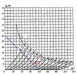
Let me think - you have about 90V across the tube and you want some dynamic headroom at the grid, say +/-2V without getting too close to grid current, so looking at the 6n23p data sheet... yep you're right you do want more current, but you might find you can get away with 6mA and still have reasonable linearity / 3rd harmonic distortion.
I see. I will try putting multiturn pot here as replacement for R17. Would you decrease or increase the current?
With your current set up the dc offset is +ve. To correct it you need to turn the VAS off slightly to allow the output to be pulled down. This means the voltage drop across R4 should be smaller - so you'd want to reduce the LTP current. That means R17 should be smaller.
Things are interrelated but the short answer is no because you are using R17 to adjust the dc-offset (which is controlled by the feedback loop). You can change R6 and move the dc operating point but then you are also changing the degeneration of the VAS.If i increase R8 and R9, do i need to adjust R6 also?
I somehow agree but can't yet tell if it's the 120VDC or bad grounding or the output power rails. Or maybe is it because my DC power lines are too close to the mains power line?
Pickup from dc power lines and ground loop noise will be at your mains frequency (50Hz or 60Hz) but power supply ripple will be twice that due to the action of the rectifiers. Can you tell whether you have mains frequency or twice mains frequency ?
View attachment 428303
Yes, i think can reduce it to around 5mA and still keep the 3K9 load as shown attached.
Lesser current requires bigger R17. I will try 100 ohm pot replacing R17, that means i can dial down to 7mA (3.5mA per tube).
Good thing i have another working amp and a function generator app on my cellphone! I compared their sound and definitely it's at mains frequency, so it's either ground loop or dc lines picking up mains hum. I tried moving the DC lines away from the mains line but can't notice any difference so i'm leaning towards more to ground loop.
Attached is my star grounding scheme. Do you see any problem? I will try removing each ground wire one-by-one and see if there's any difference.
A Newbie Tips: just found that it's easier to compare two frequencies by making them differ by 1-3 Hz. Say you want to see if it's 50Hz or 100Hz noise. Get a function generator app for your cellphone, connect the output to a working amp and set the output frequency to 52 Hz and 102 Hz. Listen carefully and see which one gives 2Hz beat-frequency.
you might find you can get away with 6mA and still have reasonable linearity / 3rd harmonic distortion.
Yes, i think can reduce it to around 5mA and still keep the 3K9 load as shown attached.
This means the voltage drop across R4 should be smaller - so you'd want to reduce the LTP current. That means R17 should be smaller.
Lesser current requires bigger R17. I will try 100 ohm pot replacing R17, that means i can dial down to 7mA (3.5mA per tube).
Pickup from dc power lines and ground loop noise will be at your mains frequency (50Hz or 60Hz) but power supply ripple will be twice that due to the action of the rectifiers. Can you tell whether you have mains frequency or twice mains frequency ?
Good thing i have another working amp and a function generator app on my cellphone! I compared their sound and definitely it's at mains frequency, so it's either ground loop or dc lines picking up mains hum. I tried moving the DC lines away from the mains line but can't notice any difference so i'm leaning towards more to ground loop.
Attached is my star grounding scheme. Do you see any problem? I will try removing each ground wire one-by-one and see if there's any difference.
A Newbie Tips: just found that it's easier to compare two frequencies by making them differ by 1-3 Hz. Say you want to see if it's 50Hz or 100Hz noise. Get a function generator app for your cellphone, connect the output to a working amp and set the output frequency to 52 Hz and 102 Hz. Listen carefully and see which one gives 2Hz beat-frequency.
Attachments
Last edited:
Member
Joined 2009
Paid Member
Are you referring to ground loop breaker?
No i haven't put any but i haven't connected any signal source either. The hum is apparent without any input, just with the power amp turning on. Besides, i have lifted the ground wire for the RCA input but hum remains. I have also lifted the ground wire coming from the mains (leaving only amp, power supply, loudspeaker terminal and DC protection grounds on the star point) but still no improvement. I'm getting suspicious about the twisted wires from the 33V rails and 120V.
I have replaced R17 (33R) with 100R trimpot and successfully reduced the offset to less than 25mV. Measuring the voltage across R4 and R5 (load resistor for the tubes), the voltages are around 30V. So 30/3900 = about 7.7mA of for idle each tube. Still reasonable for 6N23P.
Now to replace the burnt drivers (BD139-BD140) and Vbe multiplier (BD139) on the other channel (i hope the final output transistors are OK) and focus my effort on hum mitigating. By the way, it sounds more like a buzz than a hum.. does this indicate anything?
I'm hitting my head to a wall now. I've managed to kill not one, but two speakers connecting them to the amp before the DC speaker protector. That voltage offset at startup really is huge.
edit: forgot to add. I put a 120R resistor on the 120VDC line but no improvement for the hum issue.
Last edited:
Reduced the hum/buzz significantly, although it's still audible from the listening position. I tried shorting the signal input and that reduced the hum/buzz a lot. Resoldered the 470K joints and that successfully kept the hum/buzz low. I'm thinking about reducing the value to maybe 47K - 100K..
Put some back to back electrolytics between the amp and speakers till the offsets and speaker protection are working. Do you have a scope and big 8 ohm resistor you could use instead of a speaker?. Shorting the input to ground or a low impedance is a good idea till you get the grounding / screening / layout sorted.
Member
Joined 2009
Paid Member
Reduced the hum/buzz significantly,
Good work !
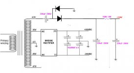
Hum is high caused by 2 points :
- Half wave doubler for B+, better use full wave doubler
- Need at least CRC filtering, even better CRCRC
Buzz is high usually due to diode switching noise, could be reduced by a snubber accross secondary of transformer.
Attached are suggestions as mentioned.
- Half wave doubler for B+, better use full wave doubler
- Need at least CRC filtering, even better CRCRC
Buzz is high usually due to diode switching noise, could be reduced by a snubber accross secondary of transformer.
Attached are suggestions as mentioned.
Attachments
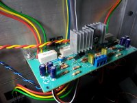
The way amplifier is made is very bad practice
Using that long leads from board to transistors is wrong
Using that type of arrangement in the cables to the outputs can and will eventually cause problems
Base cable will be at some point pick up something either from the next cables parallel with it or from any emitting device inside the case
There is a couple of small transistors on the main heat sink
Is any of them the Vbe multiplier ?
If so this is wrong
If so this one is not supposed to be there anyway
And if its there anyway expect the reaction time to be useless since its so far away from the transistors
Again in A cfp amplifier attaching the Vbe multiplier on the main heatsink will only cause trouble or bad performance
One way or another you are working with an experimental amplifier so keep the rest of your practice correct otherwise the all thing will end up in which hunt or ghost chase ...
The wiring on its own is an oscillation reason ...
It's finally done and singing beautifully!
Previously, I kept on having oscillations and they successfully killed a few speakers since my DC protection was not working. Then i remember i forgot something important: grid stopper resistors! These resistors along with the tubes' miller capacitances will form a low pass filter which prevent ultrasonics to be amplified. After i put 2K2 on each grid, there was no longer oscillation. Any value between 1K to 10K should work. Install each grid stopper as close as possible to the tube.
Hum is also close to non-existing now. I have to put my ears to only inches from the speakers to hear the hum. From my listening position, i can't hear any. What i did was i installed an RC filter on the high B+ made from 150R 2W and 220uF/200V. This RC filter is soldered on the amp PCB, not on the power supply. It's like shown on indra's suggestion, only i kept the half wave rectification.
Listening impression? This may be a biased opinion but it's beautiful! Deep and fast bass, something that was missing from my SET amp, and very detailed highs. Also female vocals are in-your-face presence. Right now the outputs are biased at 100mA but it will be increased to 1A for Class A later. Those heatsinks are barely warm now, hopefully they can withstand Class A.
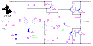
Attached is the FINAL schematic of ANUBIS and its Power Supply. Don't even think of building such hybrid amp with similar topology without any DC protection if you love your speakers. It took a good 10-15 seconds for the tubes to warm up at startup, during which there is very high DC offset at the speaker outputs.
Previously, I kept on having oscillations and they successfully killed a few speakers since my DC protection was not working. Then i remember i forgot something important: grid stopper resistors! These resistors along with the tubes' miller capacitances will form a low pass filter which prevent ultrasonics to be amplified. After i put 2K2 on each grid, there was no longer oscillation. Any value between 1K to 10K should work. Install each grid stopper as close as possible to the tube.
Hum is also close to non-existing now. I have to put my ears to only inches from the speakers to hear the hum. From my listening position, i can't hear any. What i did was i installed an RC filter on the high B+ made from 150R 2W and 220uF/200V. This RC filter is soldered on the amp PCB, not on the power supply. It's like shown on indra's suggestion, only i kept the half wave rectification.
Listening impression? This may be a biased opinion but it's beautiful! Deep and fast bass, something that was missing from my SET amp, and very detailed highs. Also female vocals are in-your-face presence. Right now the outputs are biased at 100mA but it will be increased to 1A for Class A later. Those heatsinks are barely warm now, hopefully they can withstand Class A.
Attached is the FINAL schematic of ANUBIS and its Power Supply. Don't even think of building such hybrid amp with similar topology without any DC protection if you love your speakers. It took a good 10-15 seconds for the tubes to warm up at startup, during which there is very high DC offset at the speaker outputs.
Attachments
- Status
- This old topic is closed. If you want to reopen this topic, contact a moderator using the "Report Post" button.
- Home
- Amplifiers
- Solid State
- ANUBIS - Another Tube-Transistor Hybrid Amplifier