None of those parts are going to allow measurement of bias.
If you can't find anywhere to break the circuit to measure the current then you can start with it on minimum and then by playing a low level pure tone (say 1kHz) turn the bias up until the audible distortion just disappears and leave it at that. Don't turn it any higher. Check the outputs are cool when left running for a few hours. Then check the distortion is still not present after playing it loud on music and getting it all hot.
If you can't find anywhere to break the circuit to measure the current then you can start with it on minimum and then by playing a low level pure tone (say 1kHz) turn the bias up until the audible distortion just disappears and leave it at that. Don't turn it any higher. Check the outputs are cool when left running for a few hours. Then check the distortion is still not present after playing it loud on music and getting it all hot.
None of those parts are going to allow measurement of bias.
If you can't find anywhere to break the circuit to measure the current then you can start with it on minimum and then by playing a low level pure tone (say 1kHz) turn the bias up until the audible distortion just disappears and leave it at that. Don't turn it any higher. Check the outputs are cool when left running for a few hours. Then check the distortion is still not present after playing it loud on music and getting it all hot.
OK that sounds plausible and think I can do that. Just have to figure out a way of creating a tone. Only thing I have is on my iPhone which is a signal generator, but I think that is not a good idea.
With regards to Ian Finch's comment about the large 5w resistors... they are actually 3w and .47 ohms. Are these not the emitter resistors? If so, is that not a typical place to test?
The 0.47 ohms sound just the thing. Connect your meter across one of them and slowly increase the bias. I would aim for around 5 mv initially and if that proves OK even when the amp is hot (as in no audible distortion) then leave it at that. The bias will wander a lot with temperature and the big danger is thermal runaway.
To create a tone try Audacity and a CDRW,
http://www.diyaudio.com/forums/soft...ing-using-audacity-get-you-started-guide.html
To create a tone try Audacity and a CDRW,
http://www.diyaudio.com/forums/soft...ing-using-audacity-get-you-started-guide.html
The 0.47 ohms sound just the thing. Connect your meter across one of them and slowly increase the bias. I would aim for around 5 mv initially and if that proves OK even when the amp is hot (as in no audible distortion) then leave it at that. The bias will wander a lot with temperature and the big danger is thermal runaway.
To create a tone try Audacity and a CDRW,
http://www.diyaudio.com/forums/soft...ing-using-audacity-get-you-started-guide.html
Great!! Looks like we are really getting somewhere.
Care to take a guess as to what power this baby is. I'm guessing 10w rms per channel.
Don't suppose it would be stable into a 4ohm load. Me thinks not.
Its probably fine into 4 ohms on just music. 10 wrms might be optimistic because if you really tested it for real on a sine wave then those transistors would heat rapidly. So probably the "equivalent" of a 10 watter when used sensibly.
If you know the supply voltage we can work out the maximum theoretical power.
If you know the supply voltage we can work out the maximum theoretical power.
The latest...
When measuring voltage across the large .47 ohm resistors I get only readings in AC .027V to be exact on all 4 resistors. Should I not be getting a DC reading? DC reads 0V
If I have this correct, the rails are measuring 36.5VDC.
I hooked her up tonight and hearing slight distortion in both channels. Turning the trim pots either way is not affecting this.
Right channel has a whooshing sound beginning when up at half volume. Not loud, just there, if that makes sense. I'm thinking out of spec resistor. I have checked for bad solder joints, but they appear to be good.
When measuring voltage across the large .47 ohm resistors I get only readings in AC .027V to be exact on all 4 resistors. Should I not be getting a DC reading?
DC reads 0VIf I have this correct, the rails are measuring 36.5VDC.
I hooked her up tonight and hearing slight distortion in both channels. Turning the trim pots either way is not affecting this.
Right channel has a whooshing sound beginning when up at half volume. Not loud, just there, if that makes sense. I'm thinking out of spec resistor. I have checked for bad solder joints, but they appear to be good.
Yes, you are only interested in DC. Without a circuit or actually having the unit to look at its difficult to say tbh.
We know for sure that the pots work because you mentioned that turning them caused the bulb to light and that the outputs got warm. That's exactly what should happen. Might be worth you rechecking that again to confirm it still behaves like that. Try it with a speaker too. If the bulb starts to glow and you still hear distortion then you have some other issues beyond bias at work.
We know for sure that the pots work because you mentioned that turning them caused the bulb to light and that the outputs got warm. That's exactly what should happen. Might be worth you rechecking that again to confirm it still behaves like that. Try it with a speaker too. If the bulb starts to glow and you still hear distortion then you have some other issues beyond bias at work.
It might not be relevant but some digital multimeters I've seen in recent years won't register much below 10 mV on the lowest DC voltage range.
Otherwise, why not look to see what the resistor leads connect to? If one lead is to each of the power transistors, you may have a measuring problem.
Otherwise, why not look to see what the resistor leads connect to? If one lead is to each of the power transistors, you may have a measuring problem.
Yes, you are only interested in DC. Without a circuit or actually having the unit to look at its difficult to say tbh.
We know for sure that the pots work because you mentioned that turning them caused the bulb to light and that the outputs got warm. That's exactly what should happen. Might be worth you rechecking that again to confirm it still behaves like that. Try it with a speaker too. If the bulb starts to glow and you still hear distortion then you have some other issues beyond bias at work.
It is playing normally through speaker, but slight distortion. More in the right channel when turned to half volume. Sort of whooshing sound.
When using a the DBT I do not get the bright light followed by the dim light. I get just a very dim light, almost inperseptible on a 75 watt bulb.
To Ian Finch's concerns. I have read very small voltages on other gear with this meter.
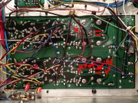
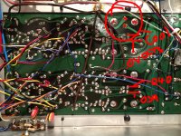
I have included images of the area in question so hopefully you guys may see something. The small circles are the contacts for the trims and the other lines indicate where the .47 ohms resistors are.
Much appreciate this help gentlemen, I know without the unit or the schematic and a complete electronic neophyt it must be a bit frustrating
Attachments
Good pics and helpful, thanks.
I can make out that the lower 0.47R resistor of each pair is connected to the collector of the lower of each pair of power transistors (that's to the bolt heads you see connecting the case/collector through the PCB). The other end of the resistor connects to the output DC point and that is the where the large output cap leading to the speaker terminals looks to be connected, as we might expect .
The upper 0.47R resistors (of each pair) are also connected to that node and though I can't really see this, it must then connect to the emitter of the upper transistor. The T03 transistor pinouts look like this:
The collector of the second transitor then connects direct to ground. In other words, it's a standard Quasi-complementary audio output stage and you definitely should see some bias current through those resistors if the amplifier bias control works as the bulb brightening suggests and you have reasonable audio.
It occurred to me that you might have had the meter set to DC current instead of voltage for this bias current measurement. (?) It does happen, since you are looking to measure current but not as such - it's the mV drop across the resistor(s) you need, and that may be treated as a current measurement, specific to the resistor used. Perhaps this is just needless advice too.
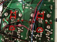
Try placing the probes across both resistors in series. i.e. measure between the right side resistor leads, (as they appear in your first pic. above, marked with the parallel lines) of each resistor pair and see what you measure as DCV then, which should simply be twice the reading across any single resistor but perhaps easier to read.
I can make out that the lower 0.47R resistor of each pair is connected to the collector of the lower of each pair of power transistors (that's to the bolt heads you see connecting the case/collector through the PCB). The other end of the resistor connects to the output DC point and that is the where the large output cap leading to the speaker terminals looks to be connected, as we might expect .
The upper 0.47R resistors (of each pair) are also connected to that node and though I can't really see this, it must then connect to the emitter of the upper transistor. The T03 transistor pinouts look like this:
The collector of the second transitor then connects direct to ground. In other words, it's a standard Quasi-complementary audio output stage and you definitely should see some bias current through those resistors if the amplifier bias control works as the bulb brightening suggests and you have reasonable audio.
It occurred to me that you might have had the meter set to DC current instead of voltage for this bias current measurement. (?) It does happen, since you are looking to measure current but not as such - it's the mV drop across the resistor(s) you need, and that may be treated as a current measurement, specific to the resistor used. Perhaps this is just needless advice too.
Try placing the probes across both resistors in series. i.e. measure between the right side resistor leads, (as they appear in your first pic. above, marked with the parallel lines) of each resistor pair and see what you measure as DCV then, which should simply be twice the reading across any single resistor but perhaps easier to read.
Well those 0.47 ohms are we are looking for. If you measure across both together (so second picture measuring across the two top connections of each pair) do you get a voltage and does that voltage vary at all ? It can be helpful to tag wires to those points and stuff them in the meter sockets to get a good connection.
Hard (impossible) to easily figure the circuit out from the print.
Hard (impossible
) to easily figure the circuit out from the print.Try placing the probes across both resistors in series. i.e. measure between the right side resistor leads, (as they appear in your first pic. above, marked with the parallel lines) of each resistor pair and see what you measure as DCV then, which should simply be twice the reading across any single resistor but perhaps easier to read.
Lol

Guys,
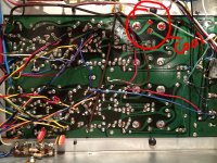
Thanks and will conduct more test based on this a advice. I seem to have got rid of the distortion by turing up the trims to where they were before I started this. What I have notice is that one of the trannies on the Left channel is cool while the other 3 are warm to the touch.
It is indicated in the pic below.
Right channel reading .039 and .040 and no voltage reading on the left. Measured across each resistor.
Attachments
Last edited:
0.04 volts across 0.47 ohm is not far off 100ma. Too high I would say for something like this.
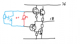
If one transistor is cold then that indicates that the mid point voltage is incorrect. On an AC coupled amp, the amplifier output (which is the junction of those 0.47 ohms) should be at about one half of the supply voltage. So that's around 18 volts on a 36 volt rail.
Edit or maybe not because the heatsink is shared by one from each channel. So maybe there is a "no bias" situation on that channel with the cold transistor.
Check the reading on both channels.
(36 volts in theory would give around 12 watts rms into 8 ohms taking into account typical losses. So you were bang on with your estimates)
0.04 volts across 0.47 ohm is not far off 100ma. Too high I would say for something like this.
If one transistor is cold then that indicates that the mid point voltage is incorrect. On an AC coupled amp, the amplifier output (which is the junction of those 0.47 ohms) should be at about one half of the supply voltage. So that's around 18 volts on a 36 volt rail.
Edit or maybe not because the heatsink is shared by one from each channel. So maybe there is a "no bias" situation on that channel with the cold transistor.
Check the reading on both channels.
(36 volts in theory would give around 12 watts rms into 8 ohms taking into account typical losses. So you were bang on with your estimates)
Not sure I follow Mooly.
One thing I know is that each terminal of each of those resistors is getting 18V.
The right channel I can read voltage across them, but not the left
The resistors seem to check out ok and not faulty.
The 18 volts is the midpoint I mentioned. So both channels are correct on that. Looks like you have a bias issue then if one channel adjusts and the other doesn't.
You need to try and draw the circuit around the preset. The way it will work is this...
The preset will allow the voltage between the two driver transistors to increase as its turned. These days a transistor is used with the pot (a vbe multiplier) but yours may be much more basic and just have the pot between the bases (perhaps with diodes or the thermistor in series with it).
Attachments
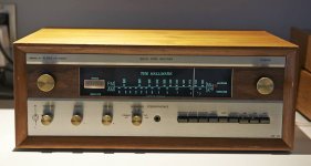
Well Mooly, been a while, but I have this baby up and running. It turned out that all that was needed was a few transistors on the amp board that needed replacing. I did a full recap, but not those funny candy coloured ones
She sounds positively delicious for an old gal. I have it at my office and playing through a pair of Elac BS123's. Excellent detail, nice extended bass and controlled highs. Sound stage is wide and detailed. Frankly a very nice little purchase for the $25.00 I paid for it. Cleaned up the cabinet as well so she even looks pretty. Pic attached.
She sounds positively delicious for an old gal. I have it at my office and playing through a pair of Elac BS123's. Excellent detail, nice extended bass and controlled highs. Sound stage is wide and detailed. Frankly a very nice little purchase for the $25.00 I paid for it. Cleaned up the cabinet as well so she even looks pretty. Pic attached.
Attachments
Last edited:
- Status
- This old topic is closed. If you want to reopen this topic, contact a moderator using the "Report Post" button.
- Home
- Amplifiers
- Solid State
- Can Anyone ID this Transistor For Me?