Hi, I have a NAD L40 CD receiver which has stopped working on the right channel regardless of the input (tuner, CD, etc)
So I swapped the speakers around but no change so it isn't the speakers.
I opened it up and swaped the fuses around, no change either & no blown fuses.
I can't see any obvious burn marks or bad capacitors etc and both channels work fine through my headphones.
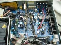
The only thing I did notice was that a transistor for the working left channel on the main board ( Q225) got fairly hot to touch but the right ( non working) side remained cold (Q226) so I presume it is faulty or something feeding it is faulty. I have attached a picture of the main board, Q226 is in a black heatsink on the bottom right.
If anyone has had a similar problem or got any ideas what is wrong I'd be much obliged for your help.
This NAD has a dedicated pre-amp out rather than jumpers so would it be OK just to use it as a tuner / CD pre-amp connected to another power amp even though it is still wired to its own internal power amp? This might be the cheaper option for me rather than an expensive repair.
Thanks for your help
So I swapped the speakers around but no change so it isn't the speakers.
I opened it up and swaped the fuses around, no change either & no blown fuses.
I can't see any obvious burn marks or bad capacitors etc and both channels work fine through my headphones.
The only thing I did notice was that a transistor for the working left channel on the main board ( Q225) got fairly hot to touch but the right ( non working) side remained cold (Q226) so I presume it is faulty or something feeding it is faulty. I have attached a picture of the main board, Q226 is in a black heatsink on the bottom right.
If anyone has had a similar problem or got any ideas what is wrong I'd be much obliged for your help.
This NAD has a dedicated pre-amp out rather than jumpers so would it be OK just to use it as a tuner / CD pre-amp connected to another power amp even though it is still wired to its own internal power amp? This might be the cheaper option for me rather than an expensive repair.
Thanks for your help
Attachments
About 95% of amplifier problems are due to output stage failures, including the very circuits designed to protect them. With one channel cold, the first thing to check is fuses M204, 205 but if they are OK as you say, the power has to be traced right to the amplifier and the relevant points in it. Here's a link to the service manual. Searching and posting one is a good way to make it easier for others to look at your problem: NAD L40 Manual - Compact Disc Receiver - HiFi Engine
This is one of NAD's weird asymmetric design output stages with Mosfet + Transistor output devices. The amplifier is AC coupled (4,700uF capacitor) so the overload protection relay only cuts the power to both channels. What you need to do is check DC voltages in the circuit to find where it went wrong. Some key DC potentials are already marked on the schematic (main board L+R ) Others can be compared with the good channel, so there is no lack of information regarding what is likely OK and what's not.
The question is, do you have the basic tools for soldering electronic circuits, small hand tools like screwdrivers, pliers etc, a DMM for accurate measurements and some grasp on the fundamentals electronics? Obviously, if parts are needed to repair the amplifier then it will cost a little money, perhaps more if trying to source obsolete parts like that BUK55 Mosfet, should it have failed. Otherwise, components are not inherently expensive, depending on where you buy and whether you wind up with fake parts which is what happens when you buy too cheap from unauthorized suppliers.
If you aren't confident or don't want to repair it, it's certainly possible to run your amp. as a preamplifier without the power amplifiers. Just remove fuses M204, 205 which removes the single +55V rail voltage supplies to each power amplifier and you still have the pre-out, as you say.
Last edited:
Let's take it one step at a time. First you'll need to get yourself a form of current limiting, such as bulb limiter, using an incandescent lamp in series with the mains to your amplifier. http://www.diyaudio.com/forums/equipment-tools/252386-bulb-limiter-testing.html
A safer to implement but perhaps expensive way, if you are not confident wiring 230V, is to solder a 220 ohm 1/2 watt resistor across the fuse holder and let that take any short currents rather than the amplifier components. It will heat quickly and burn in a fault condition if you are slow to switch off but they are cheaper than other parts. When either limiter is in place, then think about measuring.
Then make sure: No inputs or signals are selected, turn volume down to 0. Remove speakers or any other connections in or out, apart from power.
Establish whether all the transistors (apart from Mosfet) in the power amplifier are basically functional by measuring the Vbe (voltage between base & emitter) All should be ~0.65V.
Finally, watch where you place test probes and since many voltage measurements are referenced to ground, a clip for the negative probe to a ground point is safest. Then use just one hand with the positive probe for safety. There is mains power exposed in there , after all. Pressing hard with blunt probes also has a way of making them slip off the point and short out expensive bits. Take care.")
A safer to implement but perhaps expensive way, if you are not confident wiring 230V, is to solder a 220 ohm 1/2 watt resistor across the fuse holder and let that take any short currents rather than the amplifier components. It will heat quickly and burn in a fault condition if you are slow to switch off but they are cheaper than other parts. When either limiter is in place, then think about measuring.
Then make sure: No inputs or signals are selected, turn volume down to 0. Remove speakers or any other connections in or out, apart from power.
Establish whether all the transistors (apart from Mosfet) in the power amplifier are basically functional by measuring the Vbe (voltage between base & emitter) All should be ~0.65V.
Finally, watch where you place test probes and since many voltage measurements are referenced to ground, a clip for the negative probe to a ground point is safest. Then use just one hand with the positive probe for safety. There is mains power exposed in there , after all. Pressing hard with blunt probes also has a way of making them slip off the point and short out expensive bits. Take care.
OK, built a bulb limiter. With a 100w bulb briefly bright to a dull glow and then off as far as I can see. With a 60w bulb dull glow then off. I have counted 30 odd transistors on the main board so it is going to take me a while to do the measuring! I'll get back with the info in the next day or so. There is an inspection plate on the bottom of the chassis to get at the underside of the PCB so hopefully it will make the task easier.
Thanks for your help, even if it doesn't get fixed at least I have learnt something.
Thanks for your help, even if it doesn't get fixed at least I have learnt something.
At this stage, you really only need to look at the power amplifier sections shown on pages 24,25 of the manual. There are 10 bipolar transistors in each channel which should be simple to test. They will be grouped near the heatsink and not hard to identify following the schematic and odd/even numbers for left/right channels. Q211, 212 will not respond like the Bipolar transistors as they are mosfets. Simply measure and record DC voltages at their gate, drain & source pins. I'd print out the pages and write on them.
If voltages appear very close from one channel to the other there may not be a problem in that section. You generally only need to look at differences like 5% or more, and if all voltages are consistently different by a small voltage or a few %, that could well be component tolerances or possibly a single fault affecting all circuit voltages.
Good work constructing a bulb limiter. That may also come in handy if you DIY build or do more repairs. It seems you don't have any immediate problems but that can equally mean that the problem has simply blown out that section of the circuit and it no longer works nor loads the power supply. The bright glow initially is the brief surge to the transformer followed by charging the electrolytic capacitors. That's quite normal and reassuring. When it stays bright, you do have a worry.
Hi Ian,
Attached are the transistor readings but disaster has struck. On my very last reading I shorted out a pin on the right hand mosfet, bit of a spark & now the amp is is protect mode. I assume the mosfet is fried and needs a new one. I gather they aren't available so do you know an equivalent? ( I found IRLZ34 or IRLZ34N through Google) Should I change both channels?
I have taken out the fuses & the unit works through the pre amp & the headphones.
Anyway before my slip up I got three odd readings:-
Q203 (LH) and Q204 ( RH) voltages started at about 0.78v but rose slowly to well over 0.8v but never stabilizing at a steady figure As they are both doing the same this can I assume this is normal?
Q220 (RH) read either infinity or -0.43 when I swapped the probes around whereas Q219 (LH) read 0.86 This got my hopes up a bit thinking I had found the culprit, then the probe slipped on Q212.
Again thanks for the help
John
Attached are the transistor readings but disaster has struck.
On my very last reading I shorted out a pin on the right hand mosfet, bit of a spark & now the amp is is protect mode. I assume the mosfet is fried and needs a new one. I gather they aren't available so do you know an equivalent? ( I found IRLZ34 or IRLZ34N through Google) Should I change both channels?I have taken out the fuses & the unit works through the pre amp & the headphones.
Anyway before my slip up I got three odd readings:-
Q203 (LH) and Q204 ( RH) voltages started at about 0.78v but rose slowly to well over 0.8v but never stabilizing at a steady figure As they are both doing the same this can I assume this is normal?
Q220 (RH) read either infinity or -0.43 when I swapped the probes around whereas Q219 (LH) read 0.86 This got my hopes up a bit thinking I had found the culprit, then the probe slipped on Q212.
Again thanks for the help
John
Attachments
Oh dear, and we were off to a good start there.
Search at the page header for BUK555 under 'view posts' and get a feel for what and why most "equivalents" are not. This transistor has an unusually low (logic level) threshold voltage and without that feature, wannabe equivalents just won't be. There is another feature with a high Rds(on) that is considered best for audio applications and again, this just doesn't match.
The direct part is available as BUK555 60B and I would normally advise not to buy from Ebay but this guy has bailed me out of very difficult situations a few times already. The risk of cash is not much but it is still yours if there are problems: 5pcs BUK555 60B Manu PHI Encapsulation TO 220 Powermos Transistor Logic Level | eBay
Alternatives (only a few) are posted in the thread search results.
Having given you the go-to guy, we don't actually know if you have toasted anything yet. With the bulb limiter in place, only milliamps can flow so a shorted or blown device is unlikely but I guess shorting the gate would cause other problems too. The diodes (measure the voltages across these) should also be checked because they are low current devices and blow easily.
The idea was also to compare voltages between channels so that you know what to look for but this is your only reference, don't slip, get some new probes or spin them against a fine grinding wheel to grind a nice, sharp point, around 60 degrees included angle on them! (I've been known to use the knife sharpener on an electric can opener for this!) Now you see the true DIY approach
As a further precaution, heatshrink tubing on the probes with just the tips showing is good or just slip on some PVC sleeving from power flex or thin, craft plastic tubing if possible, maybe adhered with a smidgen of glue.
Let's compare voltages at the BUK555 pins and see what has happened, rechecking previous measurements at other transistors and compare the measurements with the other channel. I'm a bit concerned that you read different voltages with reversed probes though. Is the battery in your meter OK, resistance reading near zero? (about 0.3 ohms usually due to lead resistance). Grab a small battery and give that a voltage test both ways, to be certain.
I ran out of edit time but meant to first ask whether powering off then back on reset the protection switch. This gives you an indication of any damage caused. The protection circuit (actually Q216,218,220 + left channel circuit) monitors total current to each amp. by reading an excessive voltage developed across R248. It then turns off relay power and once triggered, I think it would hold that state until all power is removed so it would just turn amplifier power off again when switched on, if the overload wasn't cleared.
There is no indicator light or description of this in the owner manual either, and no connection to the microcontroller, so overload protection for the power amps is an independent circuit. The intriguing "XTALK" connections between the power amps have me stumped though - dunno how they treat cross-talk, as they appear to cross-link the amplifiers at high frequencies
It's likely that the bulb limiter, which drops mains supply voltage sharply with a load, actually alters the protection action by greatly reducing its supply voltage too. Still, we have to keep looking for what happened and clear any remaining faults.
Thanks for posting voltages you did manage to read. Most compare fine and the output devices showed no sign of failure. There is just the doubt with the odd readings that look to be failure and you realized it too. There is some damage that will have to be sorted. Unfortunately, the small transistors (2SC2240/2SA970) are now obsolete too so replacing them could be expensive due to scalping and postage . There are replacements from Fairchild (KSC1845/KSC992) but not so readily available. Still, most are in non-critical locations and substitutes won't be problem.
Hi Ian,
I took your advice & changed the battery in my meter & also opened up the L40 case a bit more to provide better access because those mosfets are really awkward to get at. I then took the readings again (and again!) and attach them to this post. Probably best to ignore the first lot. Now they are all pretty close to each other and near your original estimate. The Mosfet I sparked is still reading too and virtually the same as the working left channel.
The only anomaly is Q220 which now reads 16.5v. I checked & rechecked this so I am confident of the reading. If Q220 is part of the protection circuit & is bad maybe changing it will sort things out?
I had a look on Ebay and took a punt on two 2SC2240 for £1.68 ( 3 dollars?)
So they should be here Monday/Tuesday I hope. I know there are counterfeit components out there ( I cant get my head around that, is there a big market for obsolete semi-conductors?) but it is cheap enough for me to take a chance.
Turning it off/on with/without the bulb limiter makes no difference, the front display says 'Protect' either way. I can hear the relay click though.
If I pull both fuses it comes out of protection & works as a cd/tuner pre-amp so I am no worse off.
Thanks for your help thus far
John
Attachments
That's good news and you're right that the figures line up better with just Q220 looking bad. It's convenient that this transistor (I think) latches the relay so replacing it could just do the trick! Check the components like resistors and D2 (for 0.65V one way only) around it by measuring a few voltages around the transistor with power and then resistor values without power to see that the rest of circuit is likely ok. There may be a failed part that caused this but I think the transistors themselves there are a bit stretched to drive a power relay. They are low noise, low power (350 mW) signal amplifiers after all.
A quick comment - yes there is a thriving market for obsolete parts in audio as for any vintage collectables. People now identify old with good quality and new as throw-away junk. Fakes abound everywhere in the clamour for endless supplies of old and rare items. So when parts dry up, new old parts are made by some process and some look very convincing. Newbies who have no means of testing are easy prey for suppliers of counterfeits and unfortunately, keep them in business.
A quick comment - yes there is a thriving market for obsolete parts in audio as for any vintage collectables. People now identify old with good quality and new as throw-away junk. Fakes abound everywhere in the clamour for endless supplies of old and rare items. So when parts dry up, new old parts
are made by some process and some look very convincing. Newbies who have no means of testing are easy prey for suppliers of counterfeits and unfortunately, keep them in business.Well the transisitors finally arrived & I changed over Q220 which now reads 0.65v but the set doesn't come out of protection mode. I have checked the surrounding diodes with the power on and get the following:-
D202 0.65v
D204 0.5v
D206 0.71v
D208 1.54v
D210 0.69v
D212 0.68v
D214 10.41v ten point four one
These voltages are very similar to the left channel which did work even D214
(D215 measured 10.22v) Unless now both channels have blown?
Measuring the resistors ( power off) has proved problematic as some of the very small ones on both channels don't read on my meter or if I do briefly get a reading it quickly reads '1' on my meter
Well, we are back at about post #6 though we have some facts and figures now that look as if the amplifiers are not suffering any disasters and the similar voltage readings for each channel look encouraging.
It's not entirely clear to me, what the MCU has to do with the protection circuit (other than light a LED) and why it is presently showing active. The circuit is either omitting a link from the protection circuitry to the display/MCU board or I just can't see it. As I mentioned earlier, the protection circuits drop out the relay supplying power to both amplifiers when a fault is detected. You do have power, otherwise you wouldn't be able to measure anything at all if the protection circuit was active. What it's responding to, I can't see without taking measurements and a few tests.
You might compare DC voltages at the output, i.e at both +/- terminals of C223,4. Then let's see what current is flowing at idle, through the current sense resistors R245,6. Just measure across this 0.1 ohm resistor and the measurement will be in the region of millivolts only. You might have read in the notes for bias setting, that J235,6 are removed to allow R239,240 to be measured the same way to set bias. As they are low power resistors, you would need to be very careful that the amp. was first working normally with no or very low bias current or they would seen fry with the jumpers removed and a load connected.
Still puzzled why you have power in the protect mode
Hi Ian,
I measured C223 at 25.7v across its +/- and C224 at 26v Both R245 and R246 measured 11mv. I remeasured the Mosfets and these are virtually the same for both channels G = 27.5v D = 54v and S = 26v I tested TP 6 & TP 8 to ground and got 53.5v for both this time
I decided to do all the permutaions of the fuses M404 & M405
Ran the unit a sjust a pre amp without the fuses and it is not in protection mode.
I put the left hand channel fuse back and its still NOT in protection.
Put both fuses back and it goes into protection.
Just to check I took both fuses out again gave it a few seconds and turned it on with just the pre amp and its not in protection again.
Put the left fuse back and it stays OK, put the right fuse back and it goes into protection again.
Turned it off pulled the right fuse out and gave it a few seconds again and turned on with just the left (good channel) fuse and it stayed in protection.
So to get it out of protection I have to pull BOTH fuses and switch on as a pre amp, if I just pull the 'bad' fuse it will stay in protection mode even with the faulty channel disconnected no matter if I turn it on or off a few times.
So I am back to square one with the left channel working, only this time it goes into protection if I dont pull the right channel fuse which it didn't do originally, the right channel just didn't work but it stayed out of protection mode.
This gets interesting and you have been busy. You measure the total current to each amplifier as 11mV across 0.1R which equates to 110mA. I'm going to guess that the current to the front end of the amplifier is no more than 20mA so let's say that bias current (the remainder passing through the output transistors) is ~100mA.
Referring to the service manual, specified bias current is measured as 25-35 mV across R239/240 (TP9,10 or 11,12 with jumpers removed) which equates to only 25-35 mA. Hmmm...this has been altered, perhaps causing the protection to trip early or simply operate incorrectly.
Otherwise, I'm suggesting the small electrolytic in the protection circuit gets replaced if not already done. That's C228 in the right channel - may as well replace C226 too. Whilst there, test that none of R248,250,252,254 are open circuit.
You measure the total current to each amplifier as 11mV across 0.1R which equates to 110mA. I'm going to guess that the current to the front end of the amplifier is no more than 20mA so let's say that bias current (the remainder passing through the output transistors) is ~100mA.Referring to the service manual, specified bias current is measured as 25-35 mV across R239/240 (TP9,10 or 11,12 with jumpers removed) which equates to only 25-35 mA. Hmmm...this has been altered, perhaps causing the protection to trip early or simply operate incorrectly.
Otherwise, I'm suggesting the small electrolytic in the protection circuit gets replaced if not already done. That's C228 in the right channel - may as well replace C226 too. Whilst there, test that none of R248,250,252,254 are open circuit.
You are quite right to question C226. I meant C216, which is a 220 uF +ve rail decoupling cap. That's not essential but if you are still in progress with replacing caps, it makes sense to do as many as conveniently possible at the time. If possible, use low ESR types such as Panasonic FR, FC, FM for small values, where cost is not greatly different.......Just to confirm C226 seems to be a 33pf ceramic disc, it is shown on my diagram but I can't find it listed on the components list,which jumps from C224 to C227. It is together with C225 between the big electrolytics...C228 10uf electrolytic 63v
Hi Ian,
I have changed all the electrolytics on the right channel except the big one C224 and it has made no difference.
All the resisitors R248 250 252 & 254 are OK.
I dont know if this is significant but there were no jumpers J236 or J237 on either channel. I measured the test points anyway. The working left channel showed 3mv on my meter the non working right channel showed 5mv. I adjusted the small variable resistor until it read 3mv. ( My meter only reads down to 20 ohm on its lowest settings, perhaps I should invest in a more accurate one).
I take it the thick blue flying leads that go to pads A B D E are the ones marked on the diagram for the protection circuit? I have left them alone.
I switched everything off but on switch on the situation remains the same. The unit works without the fuses in for the power amp or with just one fuse in for the left channel. As soon as both fuses are in it goes into protection.
Should I reinstate the missing jumpers? It doesn't look like there were ever any there in the first place and the amp originally did work with out them.
I bought this unit second hand a couple of years ago as far as I know it hasn't had any work done to it.
Be careful adjusting bias. First read the power amplifier adjustment procedure carefully in the service manual - page 14. The jumpers are across TP11-TP4 in the right channel, as is the 1R R240. However, if you measure between the test points, it should read as a short due to the jumper. Note that the jumpers could also be solder links beneath the board, otherwise R240 would burn very quickly in use with even a few watts steady output as it's only a 0.25W resistor in series with the output stage current. I've no idea why both options were necessary.
As you measure a few mV across the resistors (i.e. the TPs) it tells me something is wrong and the resistors are either a lot larger than 0.25W or the solder links were not replaced. On the other hand, the meter could be in error but simply shorting the leads should amount to the same reading if the jumpers are in place as they should be.
Most meters can't even read voltages in the region of 1mV let alone with accuracy, even brand new. Specifications read like: O.1%+2 digits - which means that the error for say, 5 mV reading on a 200mV scale could be effectively +/-40%. Not good, but it's the user who has the wrong grade of instrument that is the problem. At least a 4.5 digit resolution with high accuracy is needed below 10 mV measurements and who can afford such an instrument unless it's your profession?
Let's see what's not to plan there. Check the meter by shorting its probes for a zero reading on the lowest DCV scale, what R239, 240 values are if possible and if they are just the usual tiny resistors, the status of the solder links and resolder as necessary according to the manual. Somehow though, I think this isn't the only problem
Last edited:
Hi Ian,
In my previous post I said my meter only read down to 20 ohms range, it does but I should have said 200mv range (which I am sure you guessed is what I meant) & you are right all the ones in my price range are the same. It seems to be working OK.
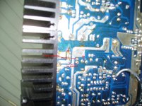
I was working to page 12 & 14 of the manual but like I said there were no jumpers in place when I opened the set up. You can see they are missing in the photo in my first post. There were no solder links either. Photo of the back of the board attached. However the set did work on both channels, I used it sparingly as a bedroom system so it was never turned up very loud.
I took out the 1 ohm resistor & measured it out of circuit at 1.5 ohm. Physically it is the same size and appearance as the majority of the others on the board, I had some new ones and they measured the same. I put a new one in and it made no difference. I have made up new jumpers & installed them again it has made no difference. The same thing happens, works as a pre-amp without the fuses, doesn't go into protection when I put in the left channel fuse but does when I then put int he right channel fuse. I have to turn it off & remove both fuses to get it out of protection.
As you probably know the 4 blue flying leads go to an earth track which runs across the main board front to back. The speaker -ives are soldered to this track too.
Idle on both channels is still 3mv on my meter.
In my previous post I said my meter only read down to 20 ohms range, it does but I should have said 200mv range (which I am sure you guessed is what I meant) & you are right all the ones in my price range are the same. It seems to be working OK.
I was working to page 12 & 14 of the manual but like I said there were no jumpers in place when I opened the set up. You can see they are missing in the photo in my first post. There were no solder links either. Photo of the back of the board attached. However the set did work on both channels, I used it sparingly as a bedroom system so it was never turned up very loud.
I took out the 1 ohm resistor & measured it out of circuit at 1.5 ohm. Physically it is the same size and appearance as the majority of the others on the board, I had some new ones and they measured the same. I put a new one in and it made no difference. I have made up new jumpers & installed them again it has made no difference. The same thing happens, works as a pre-amp without the fuses, doesn't go into protection when I put in the left channel fuse but does when I then put int he right channel fuse. I have to turn it off & remove both fuses to get it out of protection.
As you probably know the 4 blue flying leads go to an earth track which runs across the main board front to back. The speaker -ives are soldered to this track too.
Idle on both channels is still 3mv on my meter.
Attachments
- Status
- This old topic is closed. If you want to reopen this topic, contact a moderator using the "Report Post" button.
- Home
- Amplifiers
- Solid State
- Help with NAD L40