
Glow?! It would require sqrt(5W/0R33) of current (hint: 3.9A) to overheat those resistors above the max dissipation of 5W.
You might want to focus on checking your wiring on the area highlighted below.
This area adjusts bias current for the output transistors. If bias current is too high, it might heat up the resistor. That, or your output transistors are shorted.
edit: check also the 47K / 1W resistors.
You might want to focus on checking your wiring on the area highlighted below.
An externally hosted image should be here but it was not working when we last tested it.
This area adjusts bias current for the output transistors. If bias current is too high, it might heat up the resistor. That, or your output transistors are shorted.
edit: check also the 47K / 1W resistors.
in working condition
The beast is alive!
The diode bridge, torodial transformer(250va only) and output transistors're heating more then i think they should. I measured transformer 60C, transitrors up to 90C. I suppose the output transitors bias too high. Haven't done any measuring yet.
Sound is nicely rich!
The beast is alive!
The diode bridge, torodial transformer(250va only) and output transistors're heating more then i think they should. I measured transformer 60C, transitrors up to 90C. I suppose the output transitors bias too high. Haven't done any measuring yet.
Sound is nicely rich!
An externally hosted image should be here but it was not working when we last tested it.
Last edited:
Finished casing
An externally hosted image should be here but it was not working when we last tested it.
An externally hosted image should be here but it was not working when we last tested it.
An externally hosted image should be here but it was not working when we last tested it.
noobie question...
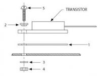
how are power and ground isolated from each other when npn's and pnp's are mounted on the same heatsink?
This is why you use insulating layer between the transistor and heatsink. The transistors must still be electrically isolated from the heatsink. Insulating layer would lower thermal efficiency but with proper dimensioning, this shouldn't be a problem. You might want to google "heatsink insulator".
This is why you use insulating layer between the transistor and heatsink. The transistors must still be electrically isolated from the heatsink. Insulating layer would lower thermal efficiency but with proper dimensioning, this shouldn't be a problem. You might want to google "heatsink insulator".
thank you ballpencil, haha good name, for the explanation!
i saw the white "layers" in the picture, between the transistors and the "copper" bar, as well as between the "copper" bar and the heatsink, and thought they are the heat conducting paste sort of stuff.
ok, we have an insulating layer now, what about the screws, would they short the transistors to the heatsink anyway? are all audio output transistors made in plastic packages only, and never with a metal tab with a hole in the middle for fastening?
are transistors with a metal tab for fastening switching power transistors, and not audio output transistors?
the white layer between the transistors and the heatsink is thick but
made out of beryllium oxide (beryllium oxide as world's best heat conductor).
PS! never drill or grind it!!!
thank you onuhannes!
is it ok to cut them?
what's the right way of making holes in them, or are we not supposed to do that either?
"never drill or grind it", ok, but what are we trying to avoid here?
Well its better not to use beryllium oxide as an insulator unless you really know how to work with it.
Use something else, that stuff isn't good for you, or the person servicing the amp in the future.
There is many other alternatives. For me +1 for good old mica")
thank you Vostro for the tip!
how do you avoid shorting threw screws?
or with real audio output transistors, that would never be an issue?
thank you Vostro for the tip!
how do you avoid shorting threw screws?
or with real audio output transistors, that would never be an issue?
You can use an insulating thinghy (#2 in image below)
Attachments
bias not clear to me
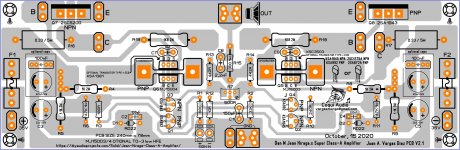
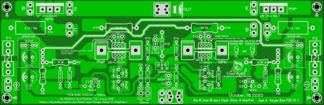
hi I'm looking for a section that covers bias on the Hiraga 30W class A this is a prototype PCB I made I chose those modern transistors but I'm not sure if I can use the values from this website I need advice oh this PCB is double layer
and here is the website link Jean Hiraga's Super Class-A Amplifier
Attachments
- Status
- This old topic is closed. If you want to reopen this topic, contact a moderator using the "Report Post" button.
- Home
- Amplifiers
- Solid State
- Hiraga 30w a class help!