Hi All,
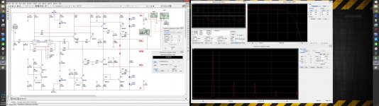
Here is my new "baby". Front-end with a vacuum tube IPS.
It is based on one of my previous (prototyped and tested) designs, with certain improvements implemented. Simulation shows very high parameters, promising a good sound.
Anybody interested in further development?")
Cheers,
Valery
Here is my new "baby". Front-end with a vacuum tube IPS.
It is based on one of my previous (prototyped and tested) designs, with certain improvements implemented. Simulation shows very high parameters, promising a good sound.
Anybody interested in further development?
Cheers,
Valery
Attachments
Member
Joined 2009
Paid Member
Hi Valery
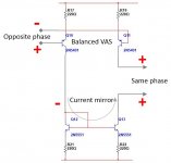
This looks rather interesting. Can you explain the function of Q10 - Q13?
Do you plan to do a PCB layout for this?
Hi Christian,
Q10-Q13 is a balanced VAS with current mirror. I tried to illustrate the principle on the attached picture. I'm not a good "artist", but hope it gives an idea of how it works
Yes, I started working on PCB.
Cheers,
Valery
Attachments
Agree - looks interesting.
What are the advantages of this over an all SS version, i.e. same topology but say, JFET instead of triode ?
Thinking about IPS LTP, I'd like to have it low-noise, highly linear and rather tolerant to high in-phase signal swing. Tube triod is actually good in all three areas. JFETs are good in SnR, but often less linear. MOSFETS are good in linearity, but not so good in SnR. So I decided to go with the best option available - give it a try and see if it really influences sonic qualities.
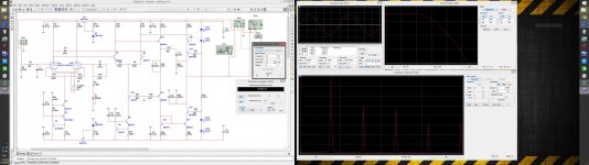
Attached is a similar output RMS as shown at the previous picture (also 20KHz), but open loop. Pretty much linear for 83db gain. Looks very promising.
Attachments
Schematic
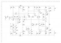
As requested - here is the schematic in both .jpg and .pdf
The node in the circle must be broken-up and connected to the power module as appropriate (it is here just for testing with no OPS purposes).
I started developing the PCB - coming soon. I am also very interested in prototyping this
As requested - here is the schematic in both .jpg and .pdf
The node in the circle must be broken-up and connected to the power module as appropriate (it is here just for testing with no OPS purposes).
I started developing the PCB - coming soon. I am also very interested in prototyping this
Attachments
Don't start with valves, I've always been curious about the little glowing things used as a small signal front end >.< Trouble is I'd want them visible haha.
Right, watching the glowing tubes is fun )
Some time ago I came across a picture somewhere on the internet, showing an amp's front panel with two windows (left <-> right) and titles under those windows:
You look at tubes <-> Tubes look at you
Hi Valery,
Are you going to do Gerbers for this too? If it will be soon I would like to include them with the Low TIM order to save on shipping time and cost.
Thanks, Terry
I'll do my best to develop them over the weekend. Will keep you posted
Valery, please add my name to the Gerber list - I'd like to order some boards too, once the design is worked through.
A few questions about the schematic:
- Can this work with lower voltages, or are the 70V rails needed for the valves?
- I know next to nothing about valves however looking at the datasheet for this device it states that DC plate voltage as 300V. Is an auxilliary power supply required?
- I don't see any rail filtering caps in the schematic. Have these been removed for Spice modelling - i.e. the actual schematic will have these components.
No one one seems to have mentioned that the output will be latched to the positive rail for the first 6 secs. or so after power up when the tube is not yet conducting. Need to have the heater supply power up about 10 secs. before the main power or something to that effect.
Valery, please add my name to the Gerber list - I'd like to order some boards too, once the design is worked through.
A few questions about the schematic:
- Can this work with lower voltages, or are the 70V rails needed for the valves?
- I know next to nothing about valves however looking at the datasheet for this device it states that DC plate voltage as 300V. Is an auxilliary power supply required?
- I don't see any rail filtering caps in the schematic. Have these been removed for Spice modelling - i.e. the actual schematic will have these components.
Yep, you're in the list )
- Right, it would be not so good having less than 60V for the valves (actual anode voltage is even less than that)
- 300V is the maximum value, we are far below
- You're right, filtering caps are not shown for modeling purposes (they increase initial setting-up significantly) - I will add them to the final schematic
No one one seems to have mentioned that the output will be latched to the positive rail for the first 6 secs. or so after power up when the tube is not yet conducting. Need to have the heater supply power up about 10 secs. before the main power or something to that effect.
Absolutely right. I will test the actual time on a prototype. I use a microcontroller-managed soft-start and protection, so adding this function will not be a problem.
As a simplest solution, delay for connecting the speakers may be increased as required.
Seems a DC speaker protection circuit would take care of that problem.
Yes, just may require a longer delay. We'll see how much longer...
I mean, it is normally combined with soft-start, providing delay before connecting the speakers at power-on
Last edited:
- Status
- This old topic is closed. If you want to reopen this topic, contact a moderator using the "Report Post" button.
- Home
- Amplifiers
- Solid State
- Low TIM, low distortion hybrid front-end