Yep, you're in the list )
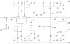
- Right, it would be not so good having less than 60V for the valves (actual anode voltage is even less than that)
- 300V is the maximum value, we are far below
- You're right, filtering caps are not shown for modeling purposes (they increase initial setting-up significantly) - I will add them to the final schematic
So we need 70V+ rails for the front end to supply the valves (more would be better?).
Would it be possible to couple this front-end to an output stage with only one or two pairs of BJT or MOSFET outputs?
So we need 70V+ rails for the front end to supply the valves (more would be better?).
Would it be possible to couple this front-end to an output stage with only one or two pairs of BJT or MOSFET outputs?
In theory, it is possible to arrange a separate (higher) power supply for the tubes and then arrange a level shift for coupling with the next stage, but it would be too complicated and somewhat pointless - the way I did it is rather simple and effective.
I set relatively low quiescent current for VAS (5.6mA), assuming rather high input impedance of the power section (with 3EF ~ 100 Kohm or so).
Significantly lower impedance will increase the level of distortion. So, in general, 2EF-BJT or MOSFET output stage is possible, but it will require certain increase of the VAS quiescent current to some 9-10mA, increasing heat dissipation requirements for the cascode (Q14, Q15 in post #9). I would use something more powerful there instead of MPSA42/92 in this case - for example KSA1381/3503. More powerful WAS will also help to drive MOSFETs with their high input capacitance.
It is possible to simulate the design you are up to and come up with optimal regime for each stage...
The problem with tubes in LTP is the startup condition.
What is the output voltage when tubes warm up?
You can easily stuck at rails. You need an output relay with delayed turn-on.
That's for sure!
the Luxman LV103/105 used the 6cg7 tubes VAS stage, you may want to check it out...
Thank you - will look at it

In theory, it is possible to arrange a separate (higher) power supply for the tubes and then arrange a level shift for coupling with the next stage, but it would be too complicated and somewhat pointless - the way I did it is rather simple and effective.
I set relatively low quiescent current for VAS (5.6mA), assuming rather high input impedance of the power section (with 3EF ~ 100 Kohm or so).
Significantly lower impedance will increase the level of distortion. So, in general, 2EF-BJT or MOSFET output stage is possible, but it will require certain increase of the VAS quiescent current to some 9-10mA, increasing heat dissipation requirements for the cascode (Q14, Q15 in post #9). I would use something more powerful there instead of MPSA42/92 in this case - for example KSA1381/3503. More powerful WAS will also help to drive MOSFETs with their high input capacitance.
It is possible to simulate the design you are up to and come up with optimal regime for each stage...
I'm thinking about coupling it to an EF3 output stage with BJT drivers and two pairs of quasi HEXFET outputs. Input impedance to the power section could be very high. Instead of level shifting, it should be possible to add current limiting protections.
I'm thinking about coupling it to an EF3 output stage with BJT drivers and two pairs of quasi HEXFET outputs. Input impedance to the power section could be very high. Instead of level shifting, it should be possible to add current limiting protections.
In this case it will be fine as is
Member
Joined 2009
Paid Member
You can combine a tube LTP with tube VAS if you want to (post 5): http://www.diyaudio.com/forums/solid-state/194268-dx-hybrid-amplifier-will-produced-soon.html
Unfortunately, I didn't get around to building it yet.
Unfortunately, I didn't get around to building it yet.
You can combine a tube LTP with tube VAS if you want to (post 5): http://www.diyaudio.com/forums/solid-state/194268-dx-hybrid-amplifier-will-produced-soon.html
Unfortunately, I didn't get around to building it yet.
Aaaahhh
") Interesting... I missed it somehow. Maybe because it started pretty long time ago I like the one in post#52 there. Maybe just needs a CCS at the bottom shoulder... keep it up!
Interesting... I missed it somehow. Maybe because it started pretty long time ago I like the one in post#52 there. Maybe just needs a CCS at the bottom shoulder... keep it up! Member
Joined 2009
Paid Member
Well I do find all these hybrid ideas very interesting and I'd like to have a go at them. You design looks very hi-end.
I didn't get around to making any hybrids yet, and over the past few weeks my brain spat out a different concept, but it also hasn't been built - it's a very clean and simple topology that is worthy of the name 'hybrid' - one of these days...
I didn't get around to making any hybrids yet, and over the past few weeks my brain spat out a different concept, but it also hasn't been built - it's a very clean and simple topology that is worthy of the name 'hybrid' - one of these days...
Last edited:
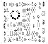
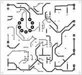
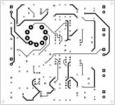
PCB!
OK, here is some documentation for you
Terry, as before - please try to check with the factory that they are ok with these gerbers as I never tried to order based on gerber format.
Just in case - the last attachment is a PCAD ASCII - that's the one I always use and this is the one I am 100% sure about. Maybe your manufacturer can use this one - it would be the most reliable option.
If you have questions, suggestions - let me know.
I will also order couple of these locally and build a prototype. Looking forward
Cheers,
Valery
Attachments
-
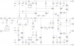 00-Tube-Hybrid-01-Sch.jpg280.8 KB · Views: 521
 -
TUBE-GERBER.zip39.1 KB · Views: 91
-
04-Tube-Hybrid-01-BOM.zip9 KB · Views: 95
-
03-Tube-Hybrid-01-Pts.pdf537.8 KB · Views: 112
-
02-Tube-Hybrid-01-Bot.pdf330 KB · Views: 117
-
01-Tube-Hybrid-01-Top.pdf308.4 KB · Views: 128
-
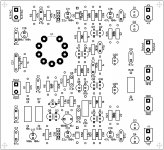 03-Tube-Hybrid-01-Pts.jpg537 KB · Views: 381
 -
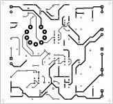 02-Tube-Hybrid-01-Bot.jpg329.2 KB · Views: 383
 -
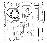 01-Tube-Hybrid-01-Top.jpg307.6 KB · Views: 427
 -
Tube-hybrid-PCAD-ASCII.zip15.5 KB · Views: 89
No one one seems to have mentioned that the output will be latched to the positive rail for the first 6 secs. or so after power up when the tube is not yet conducting. Need to have the heater supply power up about 10 secs. before the main power or something to that effect.
After some more thinking and couple of simulations - it's going to be not that bad. Balanced topology of the stages, following LTP, ensures significant in-phase signals suppression. So even with both anodes disconnected from 47k resistors, it shows -1.5V DC at the output. OK, in this situation GNFB is not working, so, assuming some components' tolerance, it may be higher. However, some current will start flowing through the valves in a few seconds, even before they heat up to normal temperature, so it will start self-balancing almost right away.
Anyway, soft-start delay will solve the problem. Prototype will show the real DC curve at the output and timing parameters
Oops! Please use this package!
Sorry - made some mistakes. Bl**dy copy/paste It's pretty late here, so...
4 resistors with wrong values, but most important - one compensation cap missing.
Here is a complete new package.
I have carefully checked everything - now it's fine.
Please use this one. My apologies for possible inconvenience
Valery
Sorry - made some mistakes. Bl**dy copy/paste
It's pretty late here, so...4 resistors with wrong values, but most important - one compensation cap missing.
Here is a complete new package.
I have carefully checked everything - now it's fine.
Please use this one. My apologies for possible inconvenience
Valery
Attachments
-
TUBE-GERBER.zip39.2 KB · Views: 96
-
04-Tube-Hybrid-01-BOM.zip9 KB · Views: 101
-
03-Tube-Hybrid-01-Pts.pdf538.4 KB · Views: 110
-
02-Tube-Hybrid-01-Bot.pdf333.1 KB · Views: 107
-
01-Tube-Hybrid-01-Top.pdf309.9 KB · Views: 106
-
 03-Tube-Hybrid-01-Pts.jpg537.6 KB · Views: 116
 -
 02-Tube-Hybrid-01-Bot.jpg332.3 KB · Views: 99
 -
 01-Tube-Hybrid-01-Top.jpg309 KB · Views: 184
 -
 00-Tube-Hybrid-01-Sch.jpg284.7 KB · Views: 392
 -
Tube-hybrid-PCAD-ASCII.zip15.6 KB · Views: 76
Very nice work, Valery!! Very nice indeed
Can you let me know the board dimensions and whether 1 oz or 2 oz plating is necessary?
The 47uF rail filters are rated 160V on the BOM. Is this intentional or would 100V electros suffice for 70V rails. Similarly for the input cap you have it rated at a high voltage. Would a nice quality film or bipolar cap rated, say 16V be suitable?
Very nice work, Valery!! Very nice indeed
Can you let me know the board dimensions and whether 1 oz or 2 oz plating is necessary?
The 47uF rail filters are rated 160V on the BOM. Is this intentional or would 100V electros suffice for 70V rails. Similarly for the input cap you have it rated at a high voltage. Would a nice quality film or bipolar cap rated, say 16V be suitable?
OK, I'm sort of... metric
Board dimensions are 120x110mm, which gives us 4.72x4.33in
I normally make the board 1.5mm (0.059in) thick with 2 or 3 oz plating. 3 oz is good for power sections, for this front-end I would do 2 oz.
Caps - you're right, these ones are a bit over-rated, in some cases I put certain ratings just to make sure I get the right dimensions on a PCB (copying from a previous, known design), in some cases slightly over-rate just for safety reasons.
So, 47uF rail filters - 100V-rated ones will be fine, nice 16V film cap at the input will be also good.
Cheers,
Valery
Thanks again Valery. Actually, Australia has been metric since the early 1970's; however, I spent some years in the UK in the 1990's, which is probably why I still think in imperial at times. It also doesn't help that some of our cars and engines here are based on American designs and use SAE fasteners.
I'm in discussions with Terry to organise a quantity of boards over the next few days. Terry will probably be the coordination point, so if anyone wants boards please let him know
I'm in discussions with Terry to organise a quantity of boards over the next few days. Terry will probably be the coordination point, so if anyone wants boards please let him know
Member
Joined 2009
Paid Member
I'm looking forward to some listening impressions from you guys on this amplifier. There aren't too many hybrids around to gather listening impressions from.
I remember the Nishiki hybrid amplifier by Wim de Haan which uses an ECC82 with 'singleton' input, buffered by cathode follower to drive a quasi-complementary SS output stage with no global feedback. However, it was, much later, modified for higher power and used an LTP input stage. But no global feedback, the inverting input of the LTP was grounded (I guess it could be used for a balanced input signal). Given that the Nishiki was said to be a good sounding amplifier it might be interesting to include some option with the amplifier of this thread - to have no global feedback. Perhaps a link to switch it from global to local feedback only ?
I remember the Nishiki hybrid amplifier by Wim de Haan which uses an ECC82 with 'singleton' input, buffered by cathode follower to drive a quasi-complementary SS output stage with no global feedback. However, it was, much later, modified for higher power and used an LTP input stage. But no global feedback, the inverting input of the LTP was grounded (I guess it could be used for a balanced input signal). Given that the Nishiki was said to be a good sounding amplifier it might be interesting to include some option with the amplifier of this thread - to have no global feedback. Perhaps a link to switch it from global to local feedback only ?
Hi Valery,
I rarely do 2oz copper. Is there some unusually high current in this design that requires it? Maybe the traces could be widened instead. Looks like there is plenty of room. The cost is almost double for 2oz and since these are usually just for testing and learning I try to keep the cost down when possible.
Let me know.
Thanks, Terry
- Status
- This old topic is closed. If you want to reopen this topic, contact a moderator using the "Report Post" button.
- Home
- Amplifiers
- Solid State
- Low TIM, low distortion hybrid front-end