Hi there,
Anyone had experience with this amp.
A love job for a friend it appears the speaker protection relay is not operating at turn on. The mains led lights up but no relay click. Friend said the same symptoms happened previously with amp & was repaired. So can someone point me at what components could be causing this, cannot find a schematic.
Cheers Johno
Usualy this hapends when are DC present to output.
It is not a simple repair like change this and this component.
First is need to check if DC it is present on OUTPUT (before relay). If yes, check the final transistors and prefinal transitors. If the final transistors are broken, check the emitors resistors too.
BUT, if you do not have experience in repairs, better ask for a experienced person.
I haven't a circuit but would venture to say its an easy fix.
Check for DC offset at the amplifier outputs. If present check for failed output devices. If these are short then most likely reason is intermittent failure of driver and VAS devices. So replace all if needed. Low value emitter resistors could have suffered so check these to. Identify the type of output stage, EF or CFP and set the bias in the right ballpark for such a stage. And use a bulb tester while diagnosing and working on the amp.
Check for DC offset at the amplifier outputs. If present check for failed output devices. If these are short then most likely reason is intermittent failure of driver and VAS devices. So replace all if needed. Low value emitter resistors could have suffered so check these to. Identify the type of output stage, EF or CFP and set the bias in the right ballpark for such a stage. And use a bulb tester while diagnosing and working on the amp.
Final stage
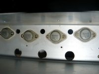
According to user guide is a emitter grounded inverted darlington pair from 1970's. The finals are a pair per channel of 2SD180/2SA626.
Can confirm the relay coil for the o/p protection has no supply across it.
Without a cct I think I'm stumped is it worth taking some voltage measurements across the output devices & posting them ?
Cheers Johno.
There's usually plenty of old threads here with references to any available info.
http://www.diyaudio.com/forums/solid-state/209789-hitachi-stereo-amplifier-ha-250-a-2.html
Have a look at post #20 suggestion and others.
http://www.diyaudio.com/forums/solid-state/209789-hitachi-stereo-amplifier-ha-250-a-2.html
Have a look at post #20 suggestion and others.
Thanks
I found that attached thread very helpful cheers.
Another post I found helpful too. Specifically comments at the bottom of thread. Hitachi HA-250 | whathifi.com
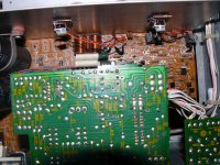
Found that SCR which controls the relay coil for the speaker protection & removed it. The SCR is located left of the power transistors - TO-220 packages (2 off) now the relay kicks in (very good, but why ?)
I then measured the DC offset on spkr outputs & there was 90mV on 1 channel & 45mV on the other. I removed the 4 output devices & they measured OK dc wise no collector / emitter shorts. Found the idle current as you suggested across the output emitter resistors was high approx 50mV (50mA) on both ch's, have moved this back to 22mV (22mA) as recommended. The amp seems stable enough over a 4 hour period of running I wonder if you think that 90mV DC offset is too high I guess this would amount to 1/8W of spkr coil power across 8 ohm spkr. Is it likely to be a problem ? Other than that it appears to sound OK through speakers
Cheers Johno.
PS Nice part of the world Coffs Harbour.
I found that attached thread very helpful cheers.
Another post I found helpful too. Specifically comments at the bottom of thread. Hitachi HA-250 | whathifi.com
Found that SCR which controls the relay coil for the speaker protection & removed it. The SCR is located left of the power transistors - TO-220 packages (2 off) now the relay kicks in (very good, but why ?)
I then measured the DC offset on spkr outputs & there was 90mV on 1 channel & 45mV on the other. I removed the 4 output devices & they measured OK dc wise no collector / emitter shorts. Found the idle current as you suggested across the output emitter resistors was high approx 50mV (50mA) on both ch's, have moved this back to 22mV (22mA) as recommended. The amp seems stable enough over a 4 hour period of running I wonder if you think that 90mV DC offset is too high I guess this would amount to 1/8W of spkr coil power across 8 ohm spkr. Is it likely to be a problem ? Other than that it appears to sound OK through speakers
Cheers Johno.
PS Nice part of the world Coffs Harbour.
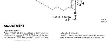
Found the idle current as you suggested across the output emitter resistors was high approx 50mV (50mA) on both ch's, have moved this back to 22mV (22mA) as recommended.
I do not have/know exatly the schematic for HA-250 but from photo looks exatly like HA-330 which I have opened on my working table for revival.
For HA-330 the idle current need to be adjusted to have 8mV±4mV on emitor resistance which it is by the way 0.22Ω. This means that you set the current to 100mA and not to 22mA for 22mV.
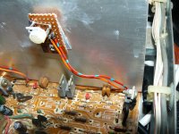
On my amplifier I put supplementary in parallel with the original circuit, a multiplied diode thermaly connected with the heatsink of the power transistors for a better idle current stabilization (original circuit it is thermaly connected to predriver and not with power transistors).
At HA-330 the SCR it is for output short circuit and SOA protection and not for DC out protection. Check the values of resistors around this SCR.
Last edited:
If you even found 50 mV (> 200 mA when measured over one 0.22R resistor -- I = V/R) originally, chances are that the bias pot has contact issues and should be cleaned / replaced (in which case I'd contemplate going multiturn). Not uncommon in Hitachi amps. Excessive quiescent current makes the output transistors much more susceptible to secondary breakdown due to heating.
Most Japanese amps run 30-50 mA of idle current, mainly for thermal considerations.
Most Japanese amps run 30-50 mA of idle current, mainly for thermal considerations.
Please check what I wrote here:
I do not have/know exatly the schematic for HA-250 but from photo looks exatly like HA-330 which I have opened on my working table for revival.
For HA-330 the idle current need to be adjusted to have 8mV±4mV on emitor resistance which it is by the way 0.22Ω.(according to service manual)
This means that you set the current to 100mA and not to 22mA for 22mV.
On my amplifier I put supplementary in parallel with the original circuit, a multiplied diode thermaly connected with the heatsink of the power transistors for a better idle current stabilization (original circuit it is thermaly connected to predriver and not with power transistors).
At HA-330 the SCR it is for output short circuit and SOA protection and not for DC out protection. Check the values of resistors around this SCR.
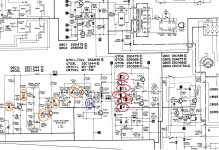
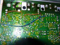
In my case the red circle resistors are devalued and need to be changed.
For your case with high DC offset, change the blue marked capacitor.
I already change most of small filtering capacitors and I must change the yellow marked capacitors.
The yellow marked I want to change because now it is sound very nice but can not be compared with my tuned Yamaha A-6A. The sound it is somehow noised even if I do not have any noise without signal.
You can see my modification too.
Attachments
-
 final amplifier.jpg330 KB · Views: 354
 -
 idle current.png28.6 KB · Views: 279
 -
 P1180370__.jpg585.5 KB · Views: 252
 -
 P1180371__.jpg497.7 KB · Views: 254
 -
 P1180372__.jpg834.5 KB · Views: 284
 -
 P1180374__.jpg106.8 KB · Views: 205
 -
 Changed schematic.png171.7 KB · Views: 198
 -
 P1180369__.jpg543.5 KB · Views: 212
Thanks for the feedback
Pictures explains a thousand words.
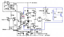
Am I correct in thinking the physical removal of SCR901 allows the base of Q901 to go low which allows the coil of RL1 to conduct thus operating the relay ? Yes will investigate the replacement of VR701 with your workaround.
Cheers Johno
Pictures explains a thousand words.
Am I correct in thinking the physical removal of SCR901 allows the base of Q901 to go low which allows the coil of RL1 to conduct thus operating the relay ? Yes will investigate the replacement of VR701 with your workaround.
Cheers Johno
When SCR901 is triggered it removes the +14 volt rail by placing what is effectively a "short" across zener diode CR802. That 14 volt rail is what turns on relay driver Q904 via base current supplied by R903. Q901, Q902 and Q903 provide DC offset protection and can disable the relay by pulling the base of Q904 low.
So there are two mechanisms. Over current detection via the SCR, which once triggered removes the 14v rail until the amp is powered off, and DC offset protection as described above.
So there are two mechanisms. Over current detection via the SCR, which once triggered removes the 14v rail until the amp is powered off, and DC offset protection as described above.
johno210 how is your amp?
I manage to finish to change all the marked components on my photos.
All "noise" and distorsion disappeared after I replaced the marked electrolitic capacitors with film capacitors 1u/63V WIMA (even in place of 3.3u and 0.47u).
Only C705 was replaced with an electrolitic.
After I replaced all devalued resistors was needed to correct resistor VR701 value from 68 to 120ohm in my workaround and I set the voltage drop across R720 to 4-5mV.
Now the sound of the amplifier it is simply awesome.
I manage to finish to change all the marked components on my photos.
The sound it is somehow noised even if I do not have any noise without signal.
All "noise" and distorsion disappeared after I replaced the marked electrolitic capacitors with film capacitors 1u/63V WIMA (even in place of 3.3u and 0.47u).
Only C705 was replaced with an electrolitic.
After I replaced all devalued resistors was needed to correct resistor VR701 value from 68 to 120ohm in my workaround and I set the voltage drop across R720 to 4-5mV.
Now the sound of the amplifier it is simply awesome.
resurrecting -- i think fixed, need advice
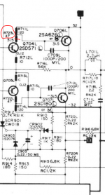
Sorry for some thread necromancy, but I was trying to fix a HA -250 myself, where the relay wasn't switching on. I removed the SCR, but that wasn't it. There was -29v on both the points just before the relay.
please see relevant portion of the ckt showing the o/p transistors.
Working backwards, i realised the issue was that R723 which is supposed 47ohms, was measuring >10megs.
The bizarre thing was that the same resistor on both channels was in this state. Replacing both makes the relay work again and both channels sound good.
But a couple of things
1. I am running it on the DBT, and the bulb (60W) does glow fairly bright in operation
2. The o/p transistors are running quite warm
3. while on the DBT the voltages that showed 29-30v (that is the unregulated rail voltage in this model) show only about 15V at relevant points
All this seems to point to some high current flow.
Hence I haven't put it directly to Mains yet.
Also, I am not sure why the two resistors failed identically. These two resistors are soldered on at the bottom of the PCB. I am not sure if some one took a lazy shortcut in the past, or it was indeed a revised circuit and the designers came up with this hack. Since these two resistors dont appear in the HA330, i am inclined to guess its a legit design change.
Any advice on what to check next?
many thanks.
- Status
- This old topic is closed. If you want to reopen this topic, contact a moderator using the "Report Post" button.
- Home
- Amplifiers
- Solid State
- Hitachi HA-250 Amp no output