I have two pairs of the original Toshiba transistors still on the hefty heatsink ( they check out as good) and the original Pioneer transformer with 75v 0v 75v secondaries.The original amp came out of a skip and had a tree growing through the centre.So no chance of restoration.
What simple amp can I build using these basic building blocks? Have looked here and at ESP but can,t find anything that exactly fits the bill. Of course I don't need to use to use the 75v transformer. Having read the data sheets for the above transistors, it appears they are capable of handling up to 200v on the collector/emitters with a possible OP of 150w. I have several hefty transformers capable of delivering this or can wind my own.
I've built a few valve amps and several simple solid state amps so not a complete beginner. Any suggestions most welcome, thanks for looking,Andy.
2pairs and 75-0-75Vac transformer is not compatible.
A 35-0-35Vac or 30-0-35Vac transformer is compatible with a 1pair output stage (2pair in a stereo amplifier).
1pair of 150W transistors is good for 70W to 80W, driving a speaker.
It could also drive a resistor to 150W, but that is not too good for music reproduction.
A 35-0-35Vac or 30-0-35Vac transformer is compatible with a 1pair output stage (2pair in a stereo amplifier).
1pair of 150W transistors is good for 70W to 80W, driving a speaker.
It could also drive a resistor to 150W, but that is not too good for music reproduction.
Last edited:
You will need spares in reserve for the day when something goes wrong. Maybe you're lucky but you'll sure be mad if you couldn't get more of this Toshiba unobtanium for when the worst happens. Don't experiment with those transistors - set the amplifier up to work properly with easily replaced MJL3281/MJL1302 types for starters and then fit the original parts if that's what you want.
2 pairs however, is only enough for say an 80W/8 ohm amplifier and that would be covered by twin power rails of around +/-45V. There are any number of designs here, fitting that sort of description but then question is, what sort of design, complexity, cost and quality are you expecting?
2 pairs however, is only enough for say an 80W/8 ohm amplifier and that would be covered by twin power rails of around +/-45V. There are any number of designs here, fitting that sort of description but then question is, what sort of design, complexity, cost and quality are you expecting?
Thanks for your replies. I think the 75v 0v 75v transformer should be saved for another project, as it is daft to get the amp to fit the PSU. Most of the simple designs of amplifiers I,ve looked at so far, that are proven run on around +/_ 30v.
Like ESP's Project 3.
I don't really need a 150w amp for home use- 60w is more than enough and will power my Mission 720's or 730's.
As to complexity,cost etc, A simple class A amp is what I,m after with a low component count. As to cost, I'm on a low budget but have a good stash of caps,resistors etc.Writting this post has focused my thoughts somewhat so I,ll leave building a 100w + amp for another day.
Andy.
IIRC, they were inside the Yamaha AX-900 (4 pairs) delivering 130W (into 8 Ohms)These are very standard (and good) transistors. Used in a lot of amplifiers of the mid 80s to 90s. You can use them in pretty much any design.
")
You can't get that with 4 transistors, unless you aim for 5W to 10W of maximum power output............... A simple class A amp is what I,m after with a low component count. ............
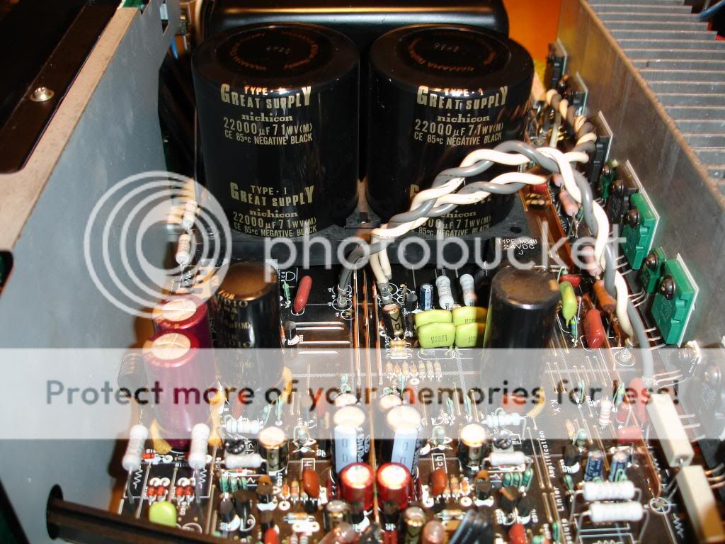
Karl's pic shows 71V capacitors. The maximum transformer voltage for those will be ~40Vac.
45-0-45Vac will overvoltage 71V caps.
Hi Andrew,
I was curious about the secondaries VAC of that massive encapsulated transformer (weights about 18 pounds the transformar alone) and, although the SM is available, it doesn't show the voltages... Any idea?


These are original Toshiba 2SC3281/A1302. You can only buy fakes of these at an acceptable price. They were EOL in 1999 and are now collectable or very expensive if genuine because some believe there is nothing as good as these for audio power transistors, even now...You can use them in pretty much any design.
That's why you don't throw them into any test or experimental project with a risk of blowing the only genuine ones you have or are ever likely to have again.
Hi Guys
Dr.Wobble, the 2SC3281-2SA1302 is an industry-standard BJT pair used in hundreds of amp designs since they were introduced so many decades ago. There are many equivalent pairs made today, so do not be phased by the hysteria above - if you happen to blow them up it is just silicon.
There are lots of good and bad designs. Be careful about minimising the parts count strictly for cost as that is false economy if you want reliability and/or high-quality sound. Of course, what YOU consider to be good sound is what matters for your project. The Rod Elliot projects are all tried and true and very basic. They can be bettered with little effort.
Build yourself a power-limiting safety socket using hardware store lamp sockets and switches. This will save a lot of money in fuses and allow real power limiting that a variac does not do as well - and the safety socket costs a lot less to build than a variac does to buy.
You can easily build 60W/ch with one pair of devices per channel, but not as class-A. However, you can set the idle current to a point that allows, say, 1W of power before transition, and that will likely be good enough for your listening room. Maybe with the Mission speakers 2W would be better.
If you wanted to build a pure class-A circuit then heat sinking and cooling become critical. Simple bias systems that directly monitor idle current will also act as overall current limits for the amp. This is not quite the same as being short-circuit-proof, but goes some way towards that. With modern amp techniques, you do not have to resort to class-A to have vanishingly low THD. Check out Doug Self's Compact blameless amp on his Signal transfer Co. site.
Ignore the naysayers and proceed carefully but with confidence.
Have fun
Kevin O'Connor
I agree, I would never use them in a DIY project either. I'd much rather keep them for if/when I came across something that used them (not unlikely) that needs repairing.These are original Toshiba 2SC3281/A1302. You can only buy fakes of these at an acceptable price. They were EOL in 1999 and are now collectable or very expensive if genuine because some believe there is nothing as good as these for audio power transistors, even now.
That's why you don't throw them into any test or experimental project with a risk of blowing the only genuine ones you have or are ever likely to have again.
The aforementioned Yamaha AX-900 is just one. AX-700, 500 and I think even AX-400 used them. Probably also used in the later AX-x50 series. Just to mention a few.
There are definitely green originals (I personally have some in an amp right here). It is possible that they stopped making green ones during the transistor's production run, however. Because that happened sometime in the 90's I believe - when this was still available.I had read Rod's(ESP) article on these and I vaguely remember he said the green ones are not genuine. I have a discarded amp board that has all black.
Last edited:
The 2SA1302/2SC3281 are very hard to find. They were replaced by Toshiba around year 2000 with the (also very very good) 2SA1943/2SC5200 pair. I have used these.
Either pair can be used for, example, a Hiraga Le Monster 30W Class A using "just" 2 pairs...
Jean Hiraga's Super Class-A Amplifier
Either pair can be used for, example, a Hiraga Le Monster 30W Class A using "just" 2 pairs...
Jean Hiraga's Super Class-A Amplifier
Yes! According to the new catalogue, they were replaced by 2SA1943N/2SC5200N
see them in page 6 in red http://www.toshiba-components.com/transistors/data/BCE0016_catalog.pdf
The new version is TO-3P.
see them in page 6 in red http://www.toshiba-components.com/transistors/data/BCE0016_catalog.pdf
The new version is TO-3P.
There is certainly no problem, but using such high speed, constant beta types in class A doesn't make use of their best qualities, which are intended for taming crossover and particularly "beta droop" distortion at high power. (see any of D. Self's amplifier books and articles for a full run-down on the topic)
Perfectly good and higher power results can be got in class A from lower frequency types like On-semi MJL21193/4/5/6 or their T03 varieties. Bangs per buck, these are much better suited to class A power. You could even include a lot of other old high power TO3 types from the MJ150xx series as more suitable too.
Perfectly good and higher power results can be got in class A from lower frequency types like On-semi MJL21193/4/5/6 or their T03 varieties. Bangs per buck, these are much better suited to class A power. You could even include a lot of other old high power TO3 types from the MJ150xx series as more suitable too.
2SA1943/2SC5200 are also discontinued.
Gajanan Phadte
But are still available from some distributors. We are organizing group buys at our local Serbian forum to buy them in spades for as low as one dollar each!
Hi Guys
Ian, you should be chastising Carver for using 1302/3281s in his horrible T-Mod amps. If one were to judge the performance of those devices based on that amp series one would never use them.
The good Dr is on a budget and has the devices in hand. Go ahead and use them in whatever design you think best. If they blow up, the MJLs work just as well in real circuits and are widely available. There are at least six complementary pairs that have near identical performance from different manufacturers. The MJLs are rated for 200W vs 150W so will have a greater safety margin in any circuit designed for the originals.
As for the original question: lots of good circuits to use these in. The Rod Elliot designs are functional and provide 1970s performance - good for many people. Those can be improved to 2000-level performance quite inexpensively as all the added parts are pennies and dimes - the big money in an amp is the chassis, heat sink, power transformer, then way down the cost list is the output devices, and much further down is all the Rs and Cs and small Qs for the front end.
Do not concern yourself with aesthetics such as "does this circuit take full advantage of the device's capabilities". Such a circuit would push the devices to the limits of their safe operating area, risking damage to them sooner than later. Then you are admonished for "risking damage to speculatively valuable devices" by wanting to use them in a circuit you build yourself or that might run them hot (class-A). All stuff to ignore.
Rod's circuits are a good starting point - not too complex and well proven. take your time building and power up the circuit carefully using the power limiting safety socket above. test open circuit and make sure everything is as it should be. Then try a bench load.
One thing to add to most circuits is a DC path to ground. This is simply a resistor of 1k to 100k depending on the output power of the amp. This provides a leakage path for the output stage and the input diff amp and helps with DC stability. DC offset is controlled easily by making the input base-leak the same value as the feedback resistor AND capacitively-coupling the input signal. No need to amplify DC.
Have fun
Kevin O'Connor
- Status
- This old topic is closed. If you want to reopen this topic, contact a moderator using the "Report Post" button.
- Home
- Amplifiers
- Solid State
- 2SC3281/2SA1302 what amp?