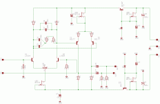
This is not a problem (I think) because the amp has no global feedback. The RIAA network is passive, sort of speaking.jewilson said:That is just too much capacitance for this poor little diff amp to slew.

peranders
When one side of the diff amp goes positive, the other side swings the opposite direction. Therefore, you still having to charge and discharge the caps. It's kind of like having your own built in Miller effect. I would be interesting to see how much voltage in could really swing and how it would react at 10-20 KHz.
When one side of the diff amp goes positive, the other side swings the opposite direction. Therefore, you still having to charge and discharge the caps. It's kind of like having your own built in Miller effect. I would be interesting to see how much voltage in could really swing and how it would react at 10-20 KHz.
I think this will be no problem. You can convince yourself if you transform the collector resistors and RIAA-network to D->Y Then you will have only collector load. This is homework, the conversion. Delta-Y conversion can be very handy when things get too complicated.
The design lacks maybe of sufficient common rejection (the pickup will pick up hum) but it may work.
The design lacks maybe of sufficient common rejection (the pickup will pick up hum) but it may work.
1) Yes Perenders, It pick some noise from pick up: if I short the input it has no noise. Have you any advice to me?
2) For my system 46.6 dB of gain is really too low. I have to raise it. I've tried to c.c. the emitter resistor of BJT but it is low yet. I don't want to use another stage.....I'll think about it.
3) What is d->conversion?


Thank you all
Aiace
2) For my system 46.6 dB of gain is really too low. I have to raise it. I've tried to c.c. the emitter resistor of BJT but it is low yet. I don't want to use another stage.....I'll think about it.
3) What is d->conversion?


Thank you all
Aiace
Somebody may give you a good reference but this is know for those who have read theory about electrical circuits.
You have tre elements connected in a triangle. You can convet this to a Y instead. This can be very neat when you want to see the real ciruit. I should say that this is essential in electronics but you don't use it every day.
If not anybody can help you here in a day or two send me a message and I can dig up some material.
This is a lot like Morrison's 'Siren Song' implemented with SS. Quite impressive, elegant, I like it.
Comments:
1. The emitter follower series power supply with FET CCS/Zener voltage reference is very nice. I've tried them and they work extremely well. Of course, this circuit really needs a good supply since the PSRR is low.
2. Is it possible to put equal emitter resistors on the input diff pair? This will give equal gain to each phase to reduce H2 to the minimum. Offset control is not a problem on this amp, and it could be trimmed to balance quite adequately by selecting input devices for the same beta and Vbe. I've found a small tip in the diff pair balance is not too damaging on the sound quality.
3. More gain could be extracted by using a bipolar input stage. I'd suggest using 2N4401/3 devices, cheap, very low noise. While this necessitates use of a quality input cap to protect the cartridge, a low voltage RTX or PPMX is fine in this role.
4. The slew issue alerted by JE Wilson looks bad to me too. Per-Anders' solution using a Y connection to ground looks good, but it may also be possible to split the RIAA, with the LF compensation in the second diff pair.
I like the elegance and simplicity, but I suspect device matching will be important. Generally I don't favor FETs for CCS, preferring bipolars with good voltage references (1.2 or 2.5 volt) or even a LED. The output caps could be Black Gate or Nichicon Muse; you can buy 25V versions in 10uF which would be ideal.
Congratulations! Nice circuit......
Cheers,
Hugh
Here is Y-D transformation... only in swedish but I think you can have use for it.
http://www.tfe.umu.se/courses/elektro/FSE/Kompendier/Y-D-transformation.pdf
Anybody who knows some cool Java calculator for this?
http://www.tfe.umu.se/courses/elektro/FSE/Kompendier/Y-D-transformation.pdf
Anybody who knows some cool Java calculator for this?
1) Thank you Peranders, I already knew D->Y transfom but in Italy it's called Star->Triangle 
2) Slew rate.... Thr slew rate is the time that you need to charge the capacitors. You can use large capacitance and low resistors or small capacitance and big resistors but the time costants are always those of the RIAA.
3) AKSA, I love you! thanks for yours compliment.
I also thought to use BJT at the input, but I have to re-design the RIAA equalitation
Thank you all
Aiace
2) Slew rate.... Thr slew rate is the time that you need to charge the capacitors. You can use large capacitance and low resistors or small capacitance and big resistors but the time costants are always those of the RIAA.

3) AKSA, I love you! thanks for yours compliment.
I also thought to use BJT at the input, but I have to re-design the RIAA equalitation

Thank you all
Aiace
Aiace said:1) Thank you Peranders, I already knew D->Y transfom but in Italy it's called Star->Triangle
Actually, I think the most common terms in swedish (after translation)
are either Star/Triangle or Star/Delta. The document P-A linked to
uses the latter of these two. D/Y is also use, where the D presumably
is an abbreviation for Delta and the Y simply reflects the actual
visual topology.
I think you can forget about slewing problems. This is only interesting when you have feedback.Aiace said:2) Slew rate.... Thr slew rate is the time that you need to charge the capacitors. You can use large capacitance and low resistors or small capacitance and big resistors but the time costants are always those of the RIAA.
About the noise, a pickup generates noise and you can't get more than 60-70 dB S/N out of a record.
The are just pulldown resistors but they may also serve as a part of a highpass filter depending of the load. Normally you should not have input or output caps hanging loose. Use always some resistor connected to ground. The capacitor can pick up charge and/or have charge which won't go away so fast. It can take hours, days... It's not harmful but if you happen to connect with power switched on you can get a nasty spike out from the speakers, headphones etc.
 I've worked hard this week and now I'm going to tell you my results:
1) I changed the input JFET with LM394. It's a dual matched BJT that give me an overall ampflication more than 60dB.
2) I resolved my noise problems. The noise generator was the shielded cable who connected the pick up to the phono amplifier. I changed it with a couple of twisted pair and the noise went away!
3) Listening impressions
My reference system is this:
-Plate is a LENCO mod L75; pick up I don't know (it was a present). There is a double delta (the smaller one inside the other) printed on it. Can anybody help me to identificate it?
-CD Player Philips CD160 (with TDA1541) twiked for zero-oversampling
-Pre Amplifier with 1 E88CC (1 triode at channel) in SE with gain matched to the amplifier
-Amplifier is an OTL made with an SRPP at channel of EL86 connected as triode
-Loudspeakers are two 800ohm Philips put into a open baffle of 80x60cm
Phono noise? What is that? I can't ear any noise now
I'm going to compare phono to CD (I can't do elsewehre). Phono sound very natual, deep firmly and fast at lowest frequencies. It gives the feeling to you of ready power to explode if necessary but always perfectly controlled.
The old TDA1514 sounds like an RX-scope: It discovers also the decays to you in mouth to the singers!
I think with a very good pick-up I can obtain the same (or more) resolution then my CD player. If it were true this phono would be advanced in all regarding my TDA1541
Thank you all
Aiace.
PS if someone wants to try to build it I can post the PCB
Hallo, Aiace,
- Did you give any chance to the FET-version? Would be interesting to compare them.
- Are you shure your Delta-Delta pickup is MM and not MC?
- Could you append the drawing of the final release, too?
- What would posting the PCB mean ? On its own or the drawing?
Regards,
Laci
- Did you give any chance to the FET-version? Would be interesting to compare them.
- Are you shure your Delta-Delta pickup is MM and not MC?
- Could you append the drawing of the final release, too?
- What would posting the PCB mean ? On its own or the drawing?
Regards,
Laci
Here the BJT schematic is. I changed only 2 resistor R10, R11 couse BJT has low input resistence.
You can use it with BJT and JFET, the RIAA (i mesuured to confirm theory) is alomost the same.
In the future I'm going to try to use 2sk170 but it's hard to find 4 matched FET at the right cost-
Hi Aiace
You can use it with BJT and JFET, the RIAA (i mesuured to confirm theory) is alomost the same.
In the future I'm going to try to use 2sk170 but it's hard to find 4 matched FET at the right cost-
Hi Aiace
Attachments
Dear Aiace,
1. The input resistance (sum of R10 and R11 parallel h21e*R1) must be 47kOhm. Check it. Also have you considered the second stage input impedance?
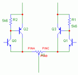
2. The input BJT quiescent current is too high (about 2mA). It is not optimal because noise contribution from the input noise current will be high. The optimal value for MM pickup is 100 uA. Without redesigning of circuit values may I suggest compound input stage:
Attachments
Thank you Dimitri for your advices....
1) Yes the input resistence should be 47k but I haven't measured it yet. I've seen a few project where you can select the input resistence, pheraps your hears could coiche the good input restence.
Sure I considered the second stage input impedance. Sure, I measure the resistence looked at the collectors of Q1 and Q2 then I calculated the RIAA then I mesured the RIAA.
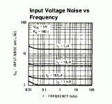
2) No noise is less with high current, the diagram from lm394 data sheet show it. Usally more current, more electrons you have and more SNR you have (i.e. in rx-tube SNR=SQRT(N) where N is number of photons that is related to the number of electrons then related to the current)
Hi Aiace
Attachments
>2) No noise is less with high current, the diagram from lm394 data sheet show it.
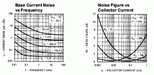
This is a big mistake. The total noise has two components: noise voltage and noise current multiplied by pickup impedance. Noise voltage of BJT is decreased with emitter current, as transconductance do (26mV/Ie), while the noise current (search for diagram!) is increased with emitter current. The optimal emitter current value for MM pickup -100uA.
This is a big mistake. The total noise has two components: noise voltage and noise current multiplied by pickup impedance. Noise voltage of BJT is decreased with emitter current, as transconductance do (26mV/Ie), while the noise current (search for diagram!) is increased with emitter current. The optimal emitter current value for MM pickup -100uA.
- Status
- This old topic is closed. If you want to reopen this topic, contact a moderator using the "Report Post" button.
- Home
- Amplifiers
- Solid State
- phono design


