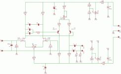
At the moment this design is only on the paper, so I can't say how good is riaa response. During simulation it should be into +/- 0.6 dB range. But simulation don't say the always the truth.
I wont to use a pseudo differention beacause my goal is to minimise common mode noise.
Now I'm workin into pcb.
Thanks
Aiace
I wont to use a pseudo differention beacause my goal is to minimise common mode noise.
Now I'm workin into pcb.
Thanks
Aiace
I thank you everybody for your help. Here are my answers and new questions.
1) In the schematic there is a mistake: I'm going to use BF244 insted BF245. What do you think about BF244 ? I know it's used in several famous disign like "volks preplifier" and many other I've found on the web
2) Yes Dimitri 10k on 80 pF probably is too high. I forgot to think at the cable capaciatace. But....I'm going to use a special cable ( I invented it ). It has 300 ohm and so it should to have 10-15 pF. I think it sholud to be to help. But probably...I'll low the output impedence. Thanks.
3) Why Giacomo do you think that if you connect R9, R8 to the ground you'll have less distortion ?
4) I forgot to say that I won't connect the ground of phono stage to the ground of Line preamplifier, but I'm going to gonnect one output (i.e. R12 ) to the ground of line amplifier and the other ( R13) to the input. So the pseudo-differetial became unbilanced.
5) Everybady told me "It's too simply!". Yes I realy wont to do it simply, 'couse more simply it is, less complonets it has and more it sound better. ( I think it has too many components for the disign that I usally I do with Tubes, but transistor needs transistrs...sigh!). What do you think about that ? And do you say it is simply couse do think it misses something?
6) Giocomo, in my schematic The RIAA EQ is between the two section.
Thank you my friends....
Aiace
1) In the schematic there is a mistake: I'm going to use BF244 insted BF245. What do you think about BF244 ? I know it's used in several famous disign like "volks preplifier" and many other I've found on the web
2) Yes Dimitri 10k on 80 pF probably is too high. I forgot to think at the cable capaciatace. But....I'm going to use a special cable ( I invented it
3) Why Giacomo do you think that if you connect R9, R8 to the ground you'll have less distortion ?
4) I forgot to say that I won't connect the ground of phono stage to the ground of Line preamplifier, but I'm going to gonnect one output (i.e. R12 ) to the ground of line amplifier and the other ( R13) to the input. So the pseudo-differetial became unbilanced.
5) Everybady told me "It's too simply!". Yes I realy wont to do it simply, 'couse more simply it is, less complonets it has and more it sound better. ( I think it has too many components for the disign that I usally I do with Tubes, but transistor needs transistrs...sigh!). What do you think about that ? And do you say it is simply couse do think it misses something?
6) Giocomo, in my schematic The RIAA EQ is between the two section.
Thank you my friends....
Aiace
Hi Aiace, " full pasive " RIAA correction give good sound results, but have big noise. Better is three amp design, with correction tau 1 + tau 2 connected between first and second amp and tau 3 between second and third amp. It have noise like feedback correction and the best sound results.
Dear Aiace
Let me warn you to think again about dc (working) points/operation conditions. You have about 50 dB of gain at dc, and several milliVolts mismatch between input JFETs will results that the outputs of your output stage will be in saturation, not in the state of active amplification. And I bet you couldn’t match JFET even with milliVolts precision. Use your brain at first not the simulator.
Ciao
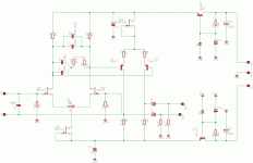
I thank you Dimitri for your advice. I think to use a pot (R1 in this schematic) to adjust the difference between the two fets.
Do you think it's enaught? If no, can you tell me what you'll do about that.
Here a new schematic, more realistic then the previus.
Bye, Aiace
Do you think it's enaught? If no, can you tell me what you'll do about that.
Here a new schematic, more realistic then the previus.
Bye, Aiace
Attachments
I object, your honour.
The circuit as detailed above runs the 431s at a noise gain of about 5, in which case they emit horrible sounds almost on a par with that other noise generator, the LM317. This can not be optimal with a payload circuit with lacking PSRR. Moreover, used as above the 431 will have an output impedance of 500-1000mOhms, a figure you can also attain easily with a well-configured BJT zener-follower (series), or its shunt equivalent.
By the way, I have a suitable breadboard with 5 or 6 styles of (simple) voltage regulators on it, all connected to a low-noise gain stage that allows me to listen to the noises on the voltage rails. (non-unity-gain) 431 and 317/337 are the worst possible solutions of the simple v-regs.
To Aiace: I think you better start with an even simpler and well-known circuit like the Pacific RIAA, or else perhaps the Pass Pearl.
I assume this is a MM phono stage. The design looks nice and interesting and I am very much looking foreward to read a first comment on its sonic performance. 
A few comments:
For more stable current sources I would recommend the BF246 (high IDss) plus a source resistor instead of the BF244.
Instead of the input BF244 you might have chosen jFETs with a higher transconductance like the 2SK369 (40ma/V) or a 2SK289 dual FET (20ma/V).
I cannot read from the schematic what currents the transistors draw. However, you should consider a battery or accumulator based power supply to eliminate the problems mentioned in the last posts.
The symmetric output allows you to place a phase switch at the output, which might be a nice option.
Good luck
KlausB

A few comments:
For more stable current sources I would recommend the BF246 (high IDss) plus a source resistor instead of the BF244.
Instead of the input BF244 you might have chosen jFETs with a higher transconductance like the 2SK369 (40ma/V) or a 2SK289 dual FET (20ma/V).
I cannot read from the schematic what currents the transistors draw. However, you should consider a battery or accumulator based power supply to eliminate the problems mentioned in the last posts.

The symmetric output allows you to place a phase switch at the output, which might be a nice option.
Good luck
KlausB
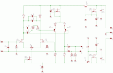
This is the final schematic that finally I built.
I've done some measures:
Gain (20Hz) = 46.6dB
Max error from RIAA +/- 0,4dB (With a little patience it can be improved but I think it's enoght for my hear)
Now I'm going to build the power supply. I'm going to post my listening impressions.
I've done some measures:
Gain (20Hz) = 46.6dB
Max error from RIAA +/- 0,4dB (With a little patience it can be improved but I think it's enoght for my hear)
Now I'm going to build the power supply. I'm going to post my listening impressions.
Attachments
- Status
- This old topic is closed. If you want to reopen this topic, contact a moderator using the "Report Post" button.
- Home
- Amplifiers
- Solid State
- phono design
 ?
?


