Hi all
I'm in the process of putting together a PSU and the LM317/337 regulators are my regulators of choice.
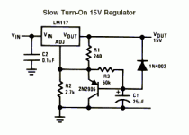
Basically i'm trying to make a slow-on design regulated at 15v with virtual ground. The datasheet for the LM317 had a design in it but i'm almost certain that the pnp transistor simply can't be flipped for the LM337 (which has nothing in it's datasheet about slow-on).
Here's what i have so far:
C4 = 0.1uf film
D2 = UF4002
VR1 = LM317
VR2 = LM337
R1 = 2.7Kohm
R2 = 240ohm
R3 = 50Kohm
D3 = 1N4004 (can't get 1N4002)
C5 = 25uf electrolytic
Q1 = 2n2905
I'm certain the negative side to the voltage regulator is wrong because of Q1b. That said is their any other transistor i can use for Q1a as well since i can't get the 2n2905. (I can get 2n2907 if they are interchangeable.)
Sorry i know very little about transistors.
I'm in the process of putting together a PSU and the LM317/337 regulators are my regulators of choice.
Basically i'm trying to make a slow-on design regulated at 15v with virtual ground. The datasheet for the LM317 had a design in it but i'm almost certain that the pnp transistor simply can't be flipped for the LM337 (which has nothing in it's datasheet about slow-on).
Here's what i have so far:
An externally hosted image should be here but it was not working when we last tested it.
C4 = 0.1uf film
D2 = UF4002
VR1 = LM317
VR2 = LM337
R1 = 2.7Kohm
R2 = 240ohm
R3 = 50Kohm
D3 = 1N4004 (can't get 1N4002)
C5 = 25uf electrolytic
Q1 = 2n2905
I'm certain the negative side to the voltage regulator is wrong because of Q1b. That said is their any other transistor i can use for Q1a as well since i can't get the 2n2905. (I can get 2n2907 if they are interchangeable.)
Sorry i know very little about transistors.
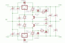
Well, I believe that every small transistor will work in this circuit. I have built it with BC327 (pnp) for LM317 and BC337 (npn) for LM337. For LM337, use npn transistor and turn all the electrolytes, compared to original schematics for LM317.
I have added 10uF capacitor accros 2.7k resistor (emitter-collector of pnp transisstor). I have also added protection diodes accross LM317 and LM337.
In case that you are interested, send me an e-mail and I will draw the complete circuit for you.
I have added 10uF capacitor accros 2.7k resistor (emitter-collector of pnp transisstor). I have also added protection diodes accross LM317 and LM337.
In case that you are interested, send me an e-mail and I will draw the complete circuit for you.
looks good. I have just one dumb question: Since I've not experienced turn-on thumps in things I've built that would take a +/-15 PS, I'm curious to know what uses benefit from slow turn on.
Mind you, the benefit is quite clear to me in the case of a power amp, but for line level stuff . . .??
Mind you, the benefit is quite clear to me in the case of a power amp, but for line level stuff . . .??
The circuit shown will reduce thumps at line-level amps based on opamps, not completely remove. This depends on circuit design and opamps used. OpAmp will start to operate when supply voltage reach some +/-2V to +/-3V. The thump is greatly reduced, as the thump swing is limited by instantly lower supply voltage. The circuit is verified and used in one of my products.
Output voltage of the slow-turn power supply rise according to exponential curve.
Output voltage of the slow-turn power supply rise according to exponential curve.
I've just read a load of stuff on how to improve LM317 and LM337. But that's not the question.
Q: Following PMA's simple desing, If I were to replace R1 (R4) with ZY type zener diodes and adjust R2 (R5) for 50 mA, do I need to adjust R3 (R6) for soft start to function properly? Also, how much time until full voltage with default value for R3 (R6).That's it. Thanks in advance.
Q: Following PMA's simple desing, If I were to replace R1 (R4) with ZY type zener diodes and adjust R2 (R5) for 50 mA, do I need to adjust R3 (R6) for soft start to function properly? Also, how much time until full voltage with default value for R3 (R6).That's it. Thanks in advance.
Slow turn on but what about Slow turn off?
This looks like a nice solution to the slow turn on problem but that's
only half of it...
How should one handle the slow turn off part?
I've seen designs that simply short the outputs of the amplifiers in
this case to prevent the turn off pop. Is there another way to achieve
this similar but opposite behavior on the power supply?
Cheers,
Chris
Well, here it is for everyone.
This looks like a nice solution to the slow turn on problem but that's
only half of it...
How should one handle the slow turn off part?
I've seen designs that simply short the outputs of the amplifiers in
this case to prevent the turn off pop. Is there another way to achieve
this similar but opposite behavior on the power supply?
Cheers,
Chris
- Status
- This old topic is closed. If you want to reopen this topic, contact a moderator using the "Report Post" button.
- Home
- Amplifiers
- Solid State
- help LM317/337 Slow-on design.

