A Low Distortion Amplifier Based on a "Tandem" Correction Scheme Powered by a Modifie
Hi there, I just needed tiny but clear sound audio power amp,
the desire led me to the schemes Fig.1 and Fig.2.
Questions, comments and suggestions for improvements are welcome.
---------------------------------------------------------
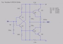
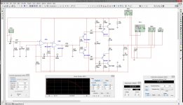
This is a low distortion simple power amplifier which works with +12V power.
The output push-pull stage of a KURODA buffer (a boot-strapped low distortion "diamond" buffer)
was modified to an inverted Dalington configuration to obtain high hFE and thus high current conduction (Fig.1).
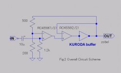
The output voltage of the buffer was followed and regulated in tandem
by two loops in one dual operational amplifier RC4558 (Fig.2).
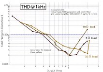
The output distortion component of a 1kHz sinusoidal wave was essentially
of second harmonic alone, assuring good quality sound.
The THD less than 0.001% was easily achievable with 5ohm load (Fig.3).
# R 1.2k in Fig.2 is mistyped. Correct value is 12k.
# C3522 in Fig1 should be read as (2S)C3422. I apologize for my mistype.
Hi there, I just needed tiny but clear sound audio power amp,
the desire led me to the schemes Fig.1 and Fig.2.
Questions, comments and suggestions for improvements are welcome.
---------------------------------------------------------
This is a low distortion simple power amplifier which works with +12V power.
The output push-pull stage of a KURODA buffer (a boot-strapped low distortion "diamond" buffer)
was modified to an inverted Dalington configuration to obtain high hFE and thus high current conduction (Fig.1).
The output voltage of the buffer was followed and regulated in tandem
by two loops in one dual operational amplifier RC4558 (Fig.2).
The output distortion component of a 1kHz sinusoidal wave was essentially
of second harmonic alone, assuring good quality sound.
The THD less than 0.001% was easily achievable with 5ohm load (Fig.3).
# R 1.2k in Fig.2 is mistyped. Correct value is 12k.
# C3522 in Fig1 should be read as (2S)C3422. I apologize for my mistype.
Attachments
Last edited:
Note on a Modification of a KURODA buffer
# the thread title should be read as
A Low Distortion Amplifier Based on a "Tandem" Correction Scheme Powered by a Modified KURODA Buffer.
Toru Kuroda explains a boot strapped emitter-follower consists of 4 Trs and 2 diodes in page 136 of his book
"Introduction to Designing Transistor Circuits" (1999, CQ Shuppan, in Japanese).
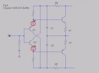
Fig.4 depicts the basic design. Collectors of Q1 and Q2 are boot-strapped via C1 and C2 (together with R4 and R6),
keeping their VCB constant, against input signal voltage.
This technique virtually cancels the Cob of Q1 and Q2 because there is no AC in their VCB and thereby reduces
possible harmonic distortion due to voltage dependent nature of Cob.
The concept is also used in the output stage of OP amps such as AD846, as Mr.Kuroda describes.
The Kuroda buffer shows very good performance.
With 6k ohm load, NOISE+THD reaches as low as 0.0004% in audio frequency region.
With heavy load, hFE of final Trs, which limit affordable output current, must be increased.
This is achievable by adapting an inverted Darlington configuration.
Another point is the elimination of emitter resistance.
Resistance 47 ohm is used in the original Kuroda buffer (Fig.4) to restrict idling current (some 10mA) corresponding to diode voltage.
By simply removing the two diodes, surprisingly, the emitter resistance was found to be minimized, even to zero ohm (Fig.1).
Be careful here that tight thermal coupling between Q1-Q5 and Q2-Q6 in Fig.1 is essential.
# the thread title should be read as
A Low Distortion Amplifier Based on a "Tandem" Correction Scheme Powered by a Modified KURODA Buffer.
Toru Kuroda explains a boot strapped emitter-follower consists of 4 Trs and 2 diodes in page 136 of his book
"Introduction to Designing Transistor Circuits" (1999, CQ Shuppan, in Japanese).
Fig.4 depicts the basic design. Collectors of Q1 and Q2 are boot-strapped via C1 and C2 (together with R4 and R6),
keeping their VCB constant, against input signal voltage.
This technique virtually cancels the Cob of Q1 and Q2 because there is no AC in their VCB and thereby reduces
possible harmonic distortion due to voltage dependent nature of Cob.
The concept is also used in the output stage of OP amps such as AD846, as Mr.Kuroda describes.
The Kuroda buffer shows very good performance.
With 6k ohm load, NOISE+THD reaches as low as 0.0004% in audio frequency region.
With heavy load, hFE of final Trs, which limit affordable output current, must be increased.
This is achievable by adapting an inverted Darlington configuration.
Another point is the elimination of emitter resistance.
Resistance 47 ohm is used in the original Kuroda buffer (Fig.4) to restrict idling current (some 10mA) corresponding to diode voltage.
By simply removing the two diodes, surprisingly, the emitter resistance was found to be minimized, even to zero ohm (Fig.1).
Be careful here that tight thermal coupling between Q1-Q5 and Q2-Q6 in Fig.1 is essential.
Attachments
Last edited:
Member
Joined 2009
Paid Member
Did you look at PSRR - I fear your modified version has a problem. When I look at this new design it almost like you have a Sziklai arrangement. Anyhow, what I see is that Q5 has an input signal defined by the voltage between it's base and emitter which encompasses the rail RC filter (3k3 resistor with cap to ground) and this will mean that the power supply ripple developed across the 'R' will be part of the signal to Q5.
Thank you Bigun-san,
cut-off f of the RC is set to be low (0.5Hz) and PSRR doesn't seem to be so bad
--- actually the power is regulated by LM317 or LM350 to 9.6V on my test board
and ripple is small on the scope screen.
I didn't know the name Sziklai ----- the pair is called as inverted/reversed Darlington
or DarlingNOT or simply a kind of compound Tr pair here in Japan.
Well, it must be called as Sziklai pair --- "S may be not pronounced? correct?
I found this page
Compound vs Darlington
Big surprise of the Fig1 circuit is that it never run away thermally.
Member
Joined 2009
Paid Member
OK good - with a regulated supply a low PSRR is a small problem, but the sound quality will depend on quality of the regulator
The Sziklai is also known by other names, often on this forum we call it 'CFP' which means Complementary Feedback Pair. In this arrangement, the thermal stability depends on the driver device not the power device. The driver device in your circuit would be the input devices - assuming I am correct even to think of this circuit as a CFP.
The Sziklai is also known by other names, often on this forum we call it 'CFP' which means Complementary Feedback Pair. In this arrangement, the thermal stability depends on the driver device not the power device. The driver device in your circuit would be the input devices - assuming I am correct even to think of this circuit as a CFP.
Hi there, I just needed tiny but clear sound audio power amp,
the desire led me to the schemes Fig.1 and Fig.2.
Questions, comments and suggestions for improvements are welcome.
---------------------------------------------------------
This is a low distortion simple power amplifier which works with +12V power.
The output push-pull stage of a KURODA buffer (a boot-strapped low distortion "diamond" buffer)
was modified to an inverted Dalington configuration to obtain high hFE and thus high current conduction (Fig.1).
The output voltage of the buffer was followed and regulated in tandem
by two loops in one dual operational amplifier RC4558 (Fig.2).
The output distortion component of a 1kHz sinusoidal wave was essentially
of second harmonic alone, promising good sound quality.
The THD less than 0.001% was easily achievable with 5ohm load (Fig.3).
# R 1.2k in Fig.2 is mistyped. Correct value is 12k.
# C3522 in Fig1 should be read as (2S)C3422. I apologize for my mistype.

I had built a similar circuit, 12 years ago, as a class A power amplifier. I liked it very much.
Class A Push-Pull Follower Czech
Class A Push-Pull Follower Czech
An externally hosted image should be here but it was not working when we last tested it.
Hi TIAEK-san,
I like tandem idea and the buffer.
I simulated your setup (with PMA's buffer, but anyway). Buffer topology ensures excellent performance at any audio frequency, however RC4558 shows not enough speed - THD @ 20KHz appears higher than 1%. I tried 2 x OPA627 - those are much faster, THD @ 20KHz = 0.005%.
Did you try to measure at 20KHz?
Cheers,
Valery
Hi, Bonsai-san, PMA-san, vzaichenko-san, I'm very glad to find big names here.
Bonsai-san
You lived in Japan. I see it all now.
Bonsai has two meanings:
1) Bon=ordinary, Sai=talent
When someone say "I'm nothing more than Bonsai", never believe the words. Just modesty, humbleness.
Very often encountered case is that he or she is actually nice person
who does high works deeply, affectionally, through continuous endeavor,
and enough talented to do that.
2) Bon=tray, Sai=plant
This is a traditional DIY hobby enjoyed in Japan for hundreds years.
To glow pines etc in a artistic form takes decades of step-by-step long-term approach.
There might be something in common between Bonsai raisers and diyaudioers.
I guess both meanings fit you.
Thanks PMA-san, you are a pioneer.
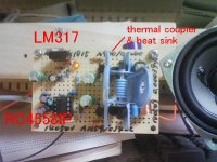
I built my circuit with +15/-15V. It works but I found final Trs got too hot.
Final R=0.2 was minimum I could do with. But distortion is still quite low.
I enjoy this 5W amp everyday.
In your case Iq=1.3A ... oh it's incredible for me but the sound should be beautiful.
My guess is a cirtain balance between VBEs, which are temperature-dependent, is important.
With lower voltage power, they work with low distortion without so much heat.
Surprising.
Thank you sim work, vzaichenko-san.
I tried NE5532, NJM5532, NJM4580, NJM4558, ... they all needed careful compensation.
I love RC4558. NJM4558 seems different one with the same number.
My tandem circuit is inspired by Sandman Class S, Technics ClassAA, and this Japanese guy
??????????????(8)???OPamp?NJM4580? - ????????????????? - Yahoo!???
(it's not me)
10kHz osc and notch filter is in prep --- I can't hear 20kHz sound.
Can it be possible to consider thermal factors in your sim?
Attached is my 12V circuit pic.
Bonsai-san
You lived in Japan. I see it all now.
Bonsai has two meanings:
1) Bon=ordinary, Sai=talent
When someone say "I'm nothing more than Bonsai", never believe the words. Just modesty, humbleness.
Very often encountered case is that he or she is actually nice person
who does high works deeply, affectionally, through continuous endeavor,
and enough talented to do that.
2) Bon=tray, Sai=plant
This is a traditional DIY hobby enjoyed in Japan for hundreds years.
To glow pines etc in a artistic form takes decades of step-by-step long-term approach.
There might be something in common between Bonsai raisers and diyaudioers.
I guess both meanings fit you.
Thanks PMA-san, you are a pioneer.
I built my circuit with +15/-15V. It works but I found final Trs got too hot.
Final R=0.2 was minimum I could do with. But distortion is still quite low.
I enjoy this 5W amp everyday.
In your case Iq=1.3A ... oh it's incredible for me but the sound should be beautiful.
My guess is a cirtain balance between VBEs, which are temperature-dependent, is important.
With lower voltage power, they work with low distortion without so much heat.
Surprising.
Thank you sim work, vzaichenko-san.
I tried NE5532, NJM5532, NJM4580, NJM4558, ... they all needed careful compensation.
I love RC4558. NJM4558 seems different one with the same number.
My tandem circuit is inspired by Sandman Class S, Technics ClassAA, and this Japanese guy
??????????????(8)???OPamp?NJM4580? - ????????????????? - Yahoo!???
(it's not me)
10kHz osc and notch filter is in prep --- I can't hear 20kHz sound.
Can it be possible to consider thermal factors in your sim?
Attached is my 12V circuit pic.
Attachments
Last edited:
- Status
- This old topic is closed. If you want to reopen this topic, contact a moderator using the "Report Post" button.
- Home
- Amplifiers
- Solid State
- A Low Distortion Amplifier Based on a "Tandem" Correction Scheme Powered by a Modifie